The NISTIR 6868 Test Part Cut with the X–Y Squareness a Laser Ball Bar Measured on Its Machine: Two Rows of Holes 6.87″ out of Square, and the Slot an Ellipse 1.64 / 1.69 µm out of Round
In 2002 David Gilsinn of NIST and Alice Ling of the Air Force Research Laboratory (AFRL) published NISTIR 6868: a production machine shop had cut 21 copies of one test part on one three-axis vertical machining centre. The machine's errors were measured first, with a laser ball bar (LBB); its X–Y squareness read −6.99, −6.43, −7.39, −6.76 and −6.79 arcseconds in five passes, a mean of −6.872″ (Table 1). The 21 parts were then measured on a coordinate measuring machine (CMM): the orthogonality fitted through the centres of two rows of milled holes averaged −1.06″, and the roundness of a circular slot's inner and outer edges 21.0 and 26.0 µm.
The report publishes no CAD model and no NC program. So an AI agent first built the part, four Fanuc programs and a HiNC project anew, following the report's Figure 2 and Appendix A, and then put the measured squareness into the machine as one error term, directly upstream of the Y axis of HiNC's skeleton three-axis machine. Not one character of the programs was changed. They were played four times at a 1 mm grid and three times at 0.25 mm, on a HiNC 3.2.46 development build with error-term branches:
- Error terms off: the nominal run. Its cut is the ideal geometry of every geometry difference (Diff) that follows.
- Error terms on, marked: the controller does not know the squareness, as on a machine that does not compensate it. This run typed in the G54 a touch-off on the real machine would find, (−585, −456, −561), which is the project's own value.
- Error terms off again, with a Diff: the control run, which measures the noise floor.
- Error terms on, mark cleared: the controller knows the squareness. The programs are plain three-axis G54/G43 programs, which should cut the same part marked or not, so this run was played once, at 1 mm, as evidence.
What came out:
- The tool tip. Each run has 55,493 steps. On every step of the marked run the tip's offset is δ = (X(cos g − 1), k·X, 0) within 2.07×10⁻¹³ mm, with k = 3.3316×10⁻⁵: where the program sends the tool to X, it goes k·X further in +Y. On the cutting steps the Y offset runs from −0.17 to +5.17 µm. The machine coordinates of the on, control and unmarked runs equal the nominal run's step for step.
- The squared holes and the orthogonality. All 24 squared holes move in +Y by k·x_c, from 0.333 µm at x 10 to 4.664 µm at x 140, within 0.0017 µm of the prediction. Fitted through the two rows of hole centres with the report's own equations 42–44, the orthogonality reads Δθ = −6.8717″; −6.872″ was put in. The diagonal from hole 3 to hole 15 grows by 3.061 µm, while 3→9 and 9→15 do not change.
- The 150 mm square. Its south wall is cut too deep and its north wall left full in proportion to x, −4.96 and +4.95 µm in the bin at x 148–150; the east and west walls do not move. The square becomes a parallelogram 6.87″ out of square.
- The slot. The whole ring moves 2.50 µm in +Y, and an ellipse rides on it: a simulated roundness of 1.640 µm on the inner edge and 1.691 µm on the outer. The plan had predicted 1.483 / 1.849 µm with the radii of the walls, so its criterion 10 fails as written on the inner wall. A wall takes the offset of the cutter centre at the moment it is cut, and the cutter centre runs on circles of 49.2625 / 50.7375 mm; with those radii the two-lobe term b2 matches within 0.0008 µm.
- Known or not, the same part. The 1 mm run with the mark cleared is bit-identical to the marked one: tool tips, machine coordinates and all 54,834 vertices of the cut.
- Against the report. The simulated part reads the −6.87″ put in. The CMM mean of −1.06″ is 5.8″ away (3.7 µm over 130 mm), 0.32 times its expanded uncertainty of 18.1″: within the uncertainty, not a match. The report's own model, −5.10 / −4.68″, includes straightness and yaw as well. The squareness accounts for 6.5–7.8 % of the roundness the CMM measured, and for none of the −11.16 µm by which the CMM found the distance 9→15 changed.
Everything here is simulated; no part was cut.
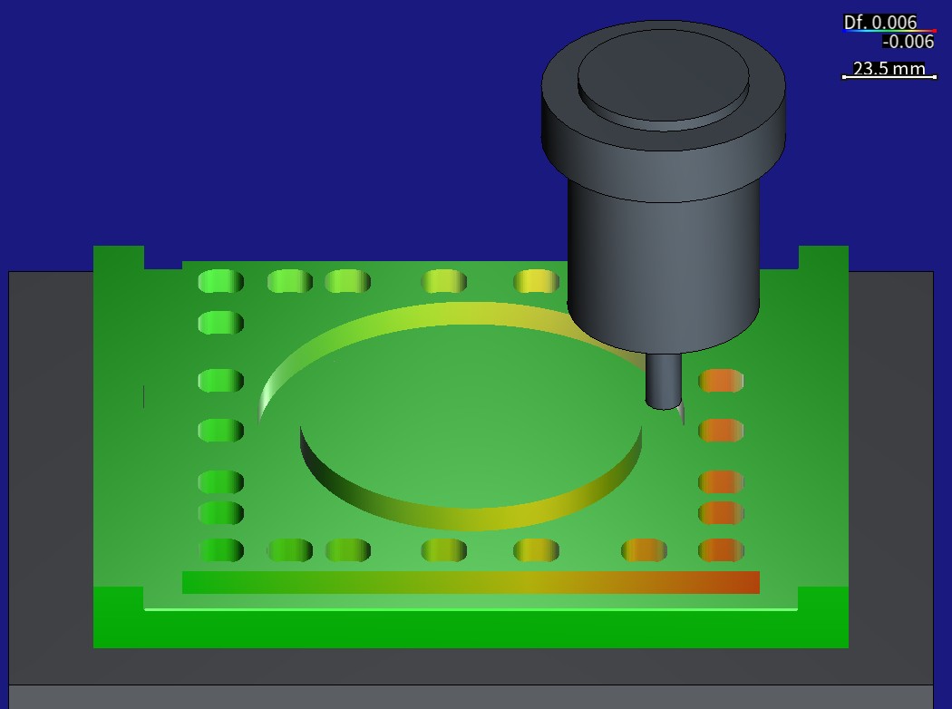
The stock the marked run recorded, put back on the canvas with its Diff, and the parking program
NC/pose-t2.nc played on it (no cut): T2, the 3/8 in end mill at 30 mm stick-out, and its ER32 collet
chuck stand in the air above the slot, the tip at X125 Y75, 5 mm above the top face. Seen from above the
front, looking +Y, the walls facing the camera — the square's south wall and the north wall of every
squared hole — run from green on the left (small x) to orange on the right (large x): cut too deep, at
most about −5 µm; the slot's far outer wall and near inner wall are yellowish (about −2.5 µm). Diff colour
scale ±0.006 mm (red = cut too deep, blue = material left, green = 0, both signs alike); 0.25 mm grid; a
HiNC 3.2.46 development build with error-term branches.
| 0.25 mm, error terms on against off, a HiNC 3.2.46 development build with error-term branches | Predicted before the first play | Measured in the simulation | The report's CMM, 21 parts |
|---|---|---|---|
| Tool tip minus nominal tip minus δ, all 55,493 steps | 0 (the plan allowed 1×10⁻⁹ mm) | largest 2.06×10⁻¹³ mm | — |
| Centre shift dy of the 24 squared holes | k·x_c, +0.333 µm (x 10) to +4.664 µm (x 140) | within 0.0017 µm of k·x_c | — |
| Orthogonality Δθ by the report's equations 42–44 | −6.872″ | −6.8717″ | −1.059″ (expanded uncertainty 18.10″) |
| Change of the hole distances 3→9 / 9→15 / 3→15 | 0 / 0 / +3.0625 µm | −0.0011 / −0.0009 / +3.0610 µm | 0.00 / −11.16 / −5.40 µm (uncertainty about 19 µm) |
| 150 mm square, slope of the south / north wall along x | −0.03332 / +0.03332 µm/mm | −0.03334 / +0.03332 µm/mm | — |
| Slot, two-lobe term b2, inner / outer | +0.7413 / −0.9245 µm with the wall radius (found after the runs: +0.8206 / −0.8452 µm with the cutter-centre radius) | +0.8199 / −0.8453 µm | — |
| Slot, roundness, inner / outer¹ | 1.4826 / 1.8491 µm with the wall radius (found after the runs: 1.6412 / 1.6904 µm with the cutter-centre radius) | 1.6398 / 1.6906 µm | 20.99 / 26.02 µm |
| Control run against the nominal cut | 0 | the steps bit-identical; every vertex within 5.0×10⁻¹⁰ mm once 14 artefacts of the distance search are rechecked as 0 | — |
¹ The simulated roundness is the second harmonic's peak-to-valley; the report's is the largest minus the smallest radius about the best-fit circle. Compare sizes only.
The case
The report (source and licence below) is the only source: a scanned PDF of 100 pages with no CAD model, no NC program and no data set; every number is printed in the report. What the agent was given:
- The machine (section 3.1): a three-axis vertical machining centre with travels of X 1020, Y 762 and Z 560 mm and a programming resolution of 0.001 mm; make, model and controller are not given. The report's model (section 4.1) has the Y slide carrying the X slide.
- Its errors: the five LBB passes of the X–Y squareness, mean −3.33×10⁻⁵ rad (Table 1), and the linear trends of the other errors over the part's range — the X and Y scale errors, straightness and yaw (Table 2).
- The part: Figure 2, a scanned drawing; the 24 hole centres of Table A1; the nominal points of the slot's two edges (Tables A2 and A3).
- The comparisons: the model's predictions (Tables 5–8 and 17) and the CMM results of the 21 parts (Tables 13–16).
- HiNC's skeleton machine
Empty-wXYOZSt, a three-axis chain without shapes (a machine with no model): the table carries X and Y, the Y slide on the X slide, and the head carries Z. The report's machine carries X on Y; the part records the angle between the two motions, which is the same whichever axis is on top. - What an error term does. An axis or the spindle of the machine can be given an error term, a branch of its own just before the axis's branch: it carries a
measured error, not design. The controller (
XyzabcSolver, which turns NC into machine coordinates) always solves on the nominal chain, taking a marked branch as no transform; while the project switch Enable Error Terms is on, the simulated machine moves, cuts and checks collisions with the marked branch. So the error is cut into the part as on a real machine whose controller does not know it: each step's machine coordinates are the same with the switch on and off, and the tool tip, the cut and the collisions differ (Error-Term Branches). Without RTCP, a tilted plane or CL playback, every error in the chain is cut into the part, marked or not. - The touch-off and P0. HiNC's program-zero measurement, P0, measures on the nominal chain; a touch-off on a real machine takes the constant shift at the touch-off pose into G54. To reproduce a given shop's result, the manual advises typing in the work offset that shop measured (work offsets on a machine with error terms).
- The request: HiNC's product owner asked for showcases of error terms, product and paper cases
alike, with the heavy work on the shared server, and agreed to build this report's test part as one of
them. The owner's ruling: an error term goes only directly upstream of a role branch — an axis X…C or
the spindle — one error per branch, on an anchor of its own named after the axis (here
Yerr).
What nothing states:
- The plate's size and thickness, and how deep the outer holes are drilled: the drawing gives no number for them (dilemma 1).
- The tools, the material, the fixture, the order of operations and the NC: the report states none of them; all are chosen.
- Whether the report's figures may be shown here: the second author's status could not be found (dilemma 2).
- The sign: the report's model carries X on Y, HiNC's skeleton Y on X; which sign the report's α takes on this skeleton has to be derived from both sides' definitions (dilemma 3).
- Where the pivot goes, so that the G54 need not change (dilemma 4).
- Whether a 0.25 mm grid reads a 1.5 µm ellipse: a cell 250 µm wide is about 150 times the ellipse.
What is new here:
- The error and the part come from one machine and one report. The LBB measured the machine that cut the 21 parts. So the simulated part can be read with the report's own methods — equations 42–44 for the orthogonality, Table 13's three distances — and the slot's ellipse with the second harmonic's peak-to-valley, and set beside the report's model and its CMM.
- The slot's ellipse follows the cutter-centre radius. The plan used the wrong radius; its criterion is judged failed as written, and the corrected prediction is given with the measured difference.
- The drilled and the squared holes move together. The report squared the outer holes to compare milled with drilled hole centres (section 3.2); that comparison cannot see the squareness.
Repeated, not new: the run with the mark cleared was actually played (1 mm), as in the roundness test part case of the same batch, and cut the same part as the marked run, bit for bit.
What the agent built
Each value is marked read (from the report), measured (on its scanned drawing), derived (computed from read values) or chosen (the agent's choice).
The base project, built through HiNC's web API on 2026-10-07, since no accepted case existed for this part:
- The part, written by a script from Figure 2 and Table A1:
- the inner 150 mm square, its walls 7 mm high (section AA), with program zero on its top face at the square's lower-left corner (section 5.1) (read);
- 24 holes drilled 9.525 mm (3/8 in), then milled into 12 mm squared holes with R4.7625 corners, 7 mm deep, their centres on x and y of 10, 28, 43, 68, 92, 120 and 140 mm (read). The numbering is the report's: hole 3 at (10, 10); the bottom row rightward 26…21, hole 21 at (140, 10); the right column upward 20…15, hole 15 at (140, 140); the top row leftward 14…9, hole 9 at (10, 140); the left column downward 8…4;
- the circular slot about (75, 75), R44.5 to R55.5, 7 mm deep (read);
- the plate, about 196 × 165 × 19 mm; the band between the square and the two side clamping flanges (x −10…0 and 150…160, 7 mm deep); the outer holes drilled at full diameter to 12.7 mm (measured on the scan against its labelled dimensions; the scan is stretched, 5.73 px/mm across and 5.09 px/mm down);
- the four small bosses inside the slot are left out: no comparison of the report uses them (chosen).
- The programs, five in Fanuc syntax, written by the agent (chosen):
NC/nist-t1-drill.nc: T1 drills the 24 holes (230 lines);NC/nist-t2-square.nc: T2 mills the band outside the square to 7 mm in two layers of 3.5 mm, climb, clockwise, each layer sweeping the two flange walls once more (52 lines);NC/nist-t2-pockets.nc: T2 mills the 24 squared holes, one pass to 7 mm, climb, counterclockwise (302 lines);NC/nist-t2-slot.nc: T2 enters helically on the slot's centreline, then mills the inner edge counterclockwise and the outer edge clockwise, the directions of section 5.4 (28 lines);NC/pose-t2.nc: a parking program for the pictures of the holder, disabled in every run.
- Tools, holder, material and fixture (chosen):
- T1, a 3/8 in 118° drill at 60 mm stick-out, S2500 F375;
- T2, a 3/8 in two-flute carbide end mill at 30 mm stick-out, S10000 F1000; its radius is the drawing's R4.7625 corner;
- both in ER32 collet chucks on SK40, tool lengths 130 and 100 mm;
- Al6061-T6, on a 240 × 200 × 20 mm plate. Physics is off in every run, so none of these changes the geometric errors this case compares.
- The machine set-up: travels X −1020…0, Y −762…0 and Z −560…0 mm (read); the plate centred on the table, which gives G54 (−585, −456, −561) (derived).
- Acceptance of the base: saved and reopened without a message, and P0 after a reset reads the G54
back; a coarse 1 mm play of 55,493 steps ends
Finishedin 30 s, with fourSys-Init--FileLinesas its only messages and no collision; no rapid line touches the stock, and every feed line of drilling and milling touches it except the entries through air, the descents along drilled holes and the returns to centre; the peak depth of cut is 7 mm. The four programs take 442 s of simulated machining time.
The error term, on a copy of the base project saved as the error-term project (its programs copied with it) and changed through the web API only:
XYsq: the X–Y squareness |
|
|---|---|
| Meaning | The +X and +Y travels meet at 90° + α. In workpiece coordinates the X travel leans 6.87″ toward +Y and the Y travel stays: where the program sends the tool to X, it lands k·X further in +Y |
| Value | α = −0.0019088889° = −6.872″ = −3.3316×10⁻⁵ rad (read: the mean of Table 1's five passes, which the report prints as −3.33E-05 rad) |
| Where | Directly upstream of the Y axis: a new anchor Yerr splits X→Y; X→Yerr carries a Static Rotation about (0, 0, 1) and is marked; the Y axis keeps its own transformer on Yerr→Y (chosen within the owner's ruling) |
| Pivot | (−585, 0, 0) in the X anchor's frame: where the tool axis stands at the touch-off pose (derived, dilemma 4) |
| Sign | Derived from the report's own definitions (dilemma 3) |
- The size is the report's, not enlarged. The five passes lie between −6.43 and −7.39″, with an estimated standard deviation of 1.67×10⁻⁶ rad (0.34″). The report's model also has X and Y scale errors (Table 2 slopes −1.89×10⁻⁵ and −1.823×10⁻⁵), straightness and yaw; they vary with position, are no fixed rigid transform, and an error term cannot hold them. The plan estimated that the linear part of Table 2's straightness, if added, would make an effective squareness of about −5.3″, a number the report does not print.
- The chain as read back after the build: table side
O→base→X→Yerr→Y→w, tool sidebase→Z→S→t. The Y axis' Dynamic Translation, axis (0, −1, 0), moved toYerr→Yunchanged, and Axis Y was bound to it again; that branch has a new guid. The other six machine branches (NewAnchor-001,X,Z,NewAnchor-006,NewAnchor-005,tooling-location) kept their names, ends, kinds, roles and guids. Eleven of the project's branches are the base's value for value;Ydiffers only in starting atYerrinstead ofX, andXYsqis new. - The sign (derived):
- The report's model writes the squareness as E_x = −y·α (equation 9). It defines the part's orthogonality as Δθ = θ2 − θ1, where θ1 is the slope of the bottom row's centres fitted as y = β0 + β1·x, and θ2 the negated slope of the left column's centres fitted as x = β0 + β1·y (equations 42–44). With α alone, Δθ = α.
- Recomputed with Table 2's coefficients, the report's whole model gives Δθ over the fourteen holes = −2.475×10⁻⁵ rad = −5.10″, exactly Table 5's value, so the definitions are read right.
- On this skeleton a rotation g about +Z upstream of Y turns the Y travel together with the table. In part coordinates the X travel leans by −g, the Y travel stays, and the tip is offset by (X(cos g − 1), −X·sin g, 0). The bottom row's centres then slope by −sin g and the left column's by 0, so Δθ = +g, and with g = α = −6.872″ the part reads the report's sign. The same batch's roundness test part case checked this formula on the same skeleton with the error placed the same way (within 1.24×10⁻¹³ mm).
- In plain words: k = −sin g = 3.3316×10⁻⁵, or 33.3 µm per metre. Where the program sends the tool to X, it lands k·X further in +Y; the +X and +Y travels meet at 90° − 6.87″. On the part, the bottom row's centres climb gradually toward +X, the left column stays, and the lower-left corner is 6.87″ short of a right angle.
- The pivot (derived): where the tool axis stands in the
Xanchor's frame at the touch-off pose, with the tip at program zero: (G54 x, 0, 0) = (−585, 0, 0). The rotation turns about that axis and program zero stays put, so a touch-off on the real machine still finds G54 (−585, −456, −561); the on and the unmarked runs typed that value in.
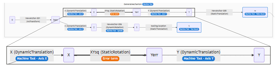
The machine-tool cluster (GeneralMechanism) in the Topology column of the equipment page. A new anchor, Yerr, stands between X and Y. XYsq, the Static Rotation on X→Yerr with the value above, is drawn bold with the orange “Error term” badge; the Y axis' Dynamic Translation sits on Yerr→Y and is still the Y axis. Below, the X→Yerr→Y stretch of the same capture, magnified. A HiNC 3.2.46 development build with error-term branches, English interface.
The predictions, written before the first play:
- The tool tip. With X the nominal run's tip x in program coordinates and k = −sin g = 3.33164×10⁻⁵: δ = Cl(on) − Cl(nominal) = (X(cos g − 1), −X·sin g, 0) = (−5.55×10⁻¹⁰·X, k·X, 0). The offset does not depend on Y or Z; it is 0 at X = 0, the program zero and touch-off point, and +4.664 µm in Y at X 140. The machine coordinates are the same step for step in all four kinds of run, since the G54 typed in is the nominal one.
- The part's surfaces, as the signed distance d of the on cut from the nominal cut (positive =
material left, negative = cut too deep):
- The squared holes move whole, by (0, k·x_c): the bottom row 3, 26, 25, 24, 23, 22, 21 by 0.333, 0.933, 1.433, 2.266, 3.065, 3.998 and 4.664 µm; the left column 3–9 all by 0.333 µm; hole 15 by 4.664 µm. A hole's south wall reads d = +k·x_c (material left), its north wall −k·x_c (cut too deep), its east and west walls 0.
- The orthogonality (equations 42–44, from 14 squared-hole centres): θ1 = +k, θ2 = 0, Δθ = −k = −6.872″.
- The 150 mm square: south wall d = −k·x, north wall +k·x, east and west walls 0.
- The slot: the plan wrote d(φ) = k(75 + 44.5 cos φ) sin φ for the inner wall and d(φ) = −k(75 + 55.5 cos φ) sin φ for the outer, φ being the azimuth about (75, 75). Fitted by harmonics, b1 = ±2.499 µm and b2 = +0.741 / −0.925 µm, a simulated roundness 2|b2| of 1.483 / 1.849 µm. The radius in those formulas should have been the cutter-centre radius (dilemma 5).
- The distances: 3→9 and 9→15 unchanged (to second order, 7×10⁻⁸ mm); 3→15 +3.063 µm; 9→21 −3.063 µm.
- The floors cut by the cutter's end, and the uncut top faces: 0.
- 84 feature boxes, each with a predicted signed mean.
The runs:
| Run | Grid | Error-term switch | XYsq | G54 | Purpose |
|---|---|---|---|---|---|
| t-nominal | 1 mm | off | marked (not in effect) | the project's (−585, −456, −561) | trimmed: nominal; exports the 1 mm nominal cut (107,570 triangles) |
| t-on | 1 mm | on | marked | typed in, (−585, −456, −561) | trimmed: on; Diff; cut exported |
| t-control | 1 mm | off | marked (not in effect) | the project's | trimmed: control; Diff; cut exported |
| t-unmarked | 1 mm | on | mark cleared | typed in, (−585, −456, −561) | trimmed: the controller knows the error; Diff; cut exported |
| f-nominal | 0.25 mm | off | marked (not in effect) | the project's | exports the nominal cut and sets it as the ideal geometry |
| f-control | 0.25 mm | off | marked (not in effect) | the project's | Diff; cut exported (the noise floor) |
| f-on | 0.25 mm | on | marked | typed in, (−585, −456, −561) | Diff; cut exported |
Every run has physics off and collision detection on (pause on failure off), plays the four cutting
programs only, with the parking program NC/pose-t2.nc disabled, and uses a Diff detect radius of 1 mm
and a colour range of ±0.006 mm. Every run but the two nominal ones records its final stock, which the
pictures put back on the canvas with its Diff.
How the agent managed the work
- The criteria came first. The plan, its predictions and twelve numbered criteria were committed 40 s before the first play, and every criterion was judged as written.
- Build and touch-off checked before the first play. The error-term project was saved as a copy of the base and changed through the web API only; its topology, value, roles and P0 were checked before any play (criteria 1 and 2).
- Coarse before fine. The trimmed set kept the programs whole and only coarsened the grid to 1 mm: four runs of about 30 s checked the step counts, the machine coordinates, the per-step formula, the control and the unmarked run (criteria 1–7), against their own 1 mm nominal cut. Then the whole part ran at 0.25 mm: nominal, control and on.
- A fresh instance for every run. The instance was restarted before every run, so each peak memory is that run's own.
- The nominal cut as the ideal geometry. The nominal run exported its cut (1,346,250 triangles at 0.25 mm) and set it as the ideal geometry of every Diff, with a detect radius of 1 mm, so the Diff holds only what the error changes, not the marks of the toolpath itself.
- Numbers from the mesh and the records. Every other run's cut was exported too and measured vertex by vertex against the nominal cut as a signed distance; a script judged criteria 3–12 from the run records, an analysis script recomputed the numbers from them, each with its source, and the vertices the distance search read farthest off were rechecked exactly against the nominal cut.
- Pictures without replaying. The Diff and holder pictures were taken in both interface languages by putting a run's recorded stock back on the canvas with its Diff; the holder pictures add the parking program.
- Sharing a server. The runs played on a private instance on a shared 32-thread server. The whole-part runs, about 100 s and under 3 GB each, ran one at a time outside the queue that heavy acceptance runs wait in, as the plan allowed for runs estimated at no more than 5 minutes and 10 GB.
- Where a person stepped in. HiNC's product owner asked for error-term showcases, paper cases welcome, agreed to add this report's test part after a search of the literature, and ruled that an error term goes only directly upstream of an axis or the spindle, one marked static branch per error. The part, the programs, where the error sits within that rule, its sign and pivot, the predictions and the criteria are the agent's own.
The dilemmas
Each one is told as its situation, the risk had it been missed, how it was noticed, the resolution, and the evidence that the resolution held.
1. The report gives a scanned drawing and tables only: the base built from the report alone
- Situation. NISTIR 6868 has no CAD and no NC, and states neither the plate's size and thickness, nor how deep the outer holes are drilled, nor the material, the tools, the cutting data, the order of operations or the fixture. Figure 2 is a scanned drawing, and a stretched one (5.73 px/mm across, 5.09 px/mm down).
- Risk. A rebuilt part that differs from the report's would make the orthogonality, the slot and the distances a different thing from what the report measured.
- How noticed. Reading the report, before the build.
- Resolution. The dimensions and tables the report labels are used as given: the 150 mm square, the hole centres of Table A1, the 12 mm squared holes with R4.7625 corners, the slot's R44.5 and R55.5 about (75, 75) from Tables A2 and A3, and the 7 mm of section AA. The plate, the band and the outer holes' drilled depth were measured on the scan against its labelled dimensions; the four small bosses were left out. The tools chosen are a 3/8 in drill and a 3/8 in end mill whose radius is the drawing's R4.7625. Every value is recorded as read, derived, chosen or measured. The three things the report compares — the two rows of squared holes, the 150 mm square and the slot — are all as drawn.
- Evidence. The base's coarse 1 mm play ran 55,493 steps with four
Sys-Init--FileLinesas its only messages and no collision; the part geometry the analysis uses equals the recorded set-up values, value for value.
2. The second author's status could not be found: no figure or table of the report is reproduced
- Situation. NIST's statement for its Technical Series says that works by NIST employees are not subject to copyright in the United States, that foreign rights are reserved, and that a reprint carries "Republished courtesy of the National Institute of Standards and Technology."; its last sentence adds that some works may have been written by third parties and be subject to copyright. The first author was at NIST; the second, A. V. Ling, is listed at AFRL/DEX.
- Risk. Reproducing the report's figures, tables or pages could infringe rights in the second author's part of the work.
- How noticed. Before the case was built (2026-10-07), checking whether the second author's part was written as a federal employee; nothing was found either way.
- Resolution. Only what no licence restricts is used: numbers, part dimensions and short quotations with their section numbers. The part is redrawn by us, every picture is a HiNC render, and the charts draw only the report's numbers, with the line NIST asks for.
- Evidence. No figure, table or page of the report appears on this page.
3. The sign: a draft's +6.87″ was wrong, and never played
- Situation. The report's α is −3.33×10⁻⁵ rad (−6.87″). The report's model carries X on Y, HiNC's skeleton Y on X; which sign a rotation about +Z upstream of Y must take, for the part to read the report's sign, has to be derived from the definitions of both.
- Risk. With the sign reversed, the part would read +6.87″, opposite to both the report's model and its CMM, and the whole comparison with the report would be wrong.
- How noticed. Before the case's design was written, by checking the report's definitions one by one: equation 9 writes E_x = −y·α, and equations 42–44 define Δθ = θ2 − θ1; the report's whole model, recomputed with Table 2's coefficients, gives Table 5's −5.10″, which confirms the reading. By that definition a rotation g on this skeleton gives the part Δθ = +g, so g = α: the draft's sign was the wrong one.
- Resolution. g = −0.0019088889° (−6.872″) went into the case, with the reason written beside it; the draft was never played.
- Evidence. Through the report's equations, the cut part reads Δθ = −6.8717″, the sign of the report's model and of its CMM mean.
4. The pivot at the touch-off's tool axis: G54 stays, and P0 reads 15.19 µm off once the mark is cleared
- Situation. Where a static rotation's pivot sits decides how far the whole part moves. A touch-off on the real machine takes the offset at the touch-off pose into G54; HiNC's P0 measures on the nominal chain and does not.
- Risk. With the pivot elsewhere the whole part would shift, and the Diff would charge the missing touch-off to the error. With the mark cleared, a G54 typed from P0's reading would give the unmarked run 15 µm of offset that no real machine has; and the failed rows of the touch-off check could be taken for a failed build.
- How noticed. The touch-off check before the plays. Marked, with the switch on or off, P0 reads (−585, −456, −561) exactly; with the mark cleared it reads (−585.01519, −455.99999975, −561).
- Resolution.
- The pivot sits where the tool axis stands at the touch-off pose, (−585, 0, 0) in the
Xanchor's frame, so program zero stays put. - Criterion 2 judges the two marked rows only; the on and the unmarked runs both typed in the G54 a real touch-off finds, (−585, −456, −561).
- The offset with the mark cleared comes from how P0 measures: it takes program zero in the tool-end frame at machine zero and does not solve the chain. At machine zero Y = 0, program zero lies 456 mm from the pivot line, and 456 mm × 3.3316×10⁻⁵ = 15.19 µm goes into X.
- The pivot sits where the tool axis stands at the touch-off pose, (−585, 0, 0) in the
- Evidence. Only the two cleared-mark rows fail the touch-off check; the affine fit of the tip offset has the constant term b = (−1.9×10⁻¹⁴, −9.3×10⁻¹⁷, 0) mm.
5. Criterion 10 fails as written: the plan used the wall radius, and a wall takes the cutter centre's offset
- Situation. The plan predicted the slot's ellipse with the wall radii 44.5 / 55.5 mm: b2 +0.741 / −0.925 µm and a simulated roundness of 1.483 / 1.849 µm, ±10 %. The inner wall measured b2 +0.8199 µm (allowed 0.667–0.815) and a roundness of 1.6398 µm (allowed 1.334–1.631), both outside; the outer wall's −0.8453 and 1.6906 µm are inside, yet 8.6 % from the plan's numbers.
- Risk. Chasing it as a fault of HiNC or of the mesh; or switching to a new prediction after the fact and turning the verdict into a pass.
- How noticed. Judging criterion 10: the inner wall outside, the outer 8.6 % off, the two walls off in opposite directions.
- Resolution.
- The verdict stays as written: failed (inner wall).
- The cause was found apart from the verdict. The tip's offset depends only on the cutter centre's x,
and each point of the wall is cut when the cutter centre stands at the same azimuth. The cutter
centre runs on a circle of R ± 4.7625 mm (
nist-t2-slot.nc's I−49.2625 and I−50.7375), so b2 = ±k·R_c/2 and the roundness is k·R_c, with R_c the cutter-centre radius. With 49.2625 / 50.7375 mm, b2 is +0.8206 / −0.8452 µm and the roundness 1.6412 / 1.6904 µm. This is recorded as the plan's error. - The predictions of the 16 slot boxes used the wall radius too: the eight at 45°, 135°, 225° and 315° read 0.076–0.087 µm off the plan (at most slot-out-315, −0.087 µm), still inside their tolerance; the +0.101 µm of slot-in-000 does not come from the radius (dilemma 7).
- The same batch's RPTU part 8 case had already found this: its Ø54 boss's two lobes follow the cutter-centre radius, 30 mm, not the boss's 27 mm. This plan did not use it.
- Evidence. b2 lies 0.0007 / 0.0001 µm from the cutter-centre prediction, the roundness 0.0014 / 0.0002 µm; in the slot chart the measurement lies on the dashed line, while the plan's dotted line is smaller on the inner wall and larger on the outer.
6. Fourteen bottom-face vertices of the control read 5.9–7.3 mm: an artefact of the search
- Situation. Criterion 7 asks every vertex of the control's cut to lie within 1×10⁻⁶ mm of the nominal cut. Of the whole-part control's 669,938 vertices, 14 read −5.86 to −7.32 mm, all on the uncut bottom face of the plate (z −19); the trimmed control had 13.
- Risk. Failing criterion 7, or believing the bottom face was cut 7 mm too deep.
- How noticed. Judging criterion 7.
- Resolution. The distance search looks only at the triangles of the 12 nearest triangle centroids, and the face these vertices lie on was not among them. Recomputed against every triangle of the nominal cut, all of them are 0.0 mm. The on run has the same 14 vertices at the same places with the same readings; recomputed exactly, they are 0 as well, and no statistic on this page includes their search readings.
- Evidence. The exact recheck finds 0 for each of them: 14 in the whole-part control, 13 in the trimmed control and the same 14 in the on run. Every other control vertex lies within 5.0×10⁻¹⁰ mm.
7. The inner wall reads up to +0.37 µm where its pass starts and ends, unexplained
- Situation. Within 1° of φ 0 on the slot's inner wall (243 vertices), the distance averages +0.079
and reaches +0.368 µm (a reading of the search, not checked exactly), where the prediction is almost 0.
The box slot-in-000 reads +0.101 µm, the largest difference of the 84 boxes from their predictions and
the only one the cutter-centre prediction does not explain. At the same place the touch flag of one
step (
IsTouched, whether the step touched material) differs between the on and the nominal run. - Risk. Reporting it as an effect of the error, or as a defect of HiNC.
- How noticed. The box residuals and the plot of every vertex against azimuth.
- Resolution. It lies inside the box's 0.3 µm tolerance and is recorded as it is. The inner pass enters radially from the helix on the centreline (X 125 → 124.2625) and returns to the same point after a full circle; the entry and exit sweeps probably overlap on the grid there, which was not verified.
- Evidence. The box slot-in-000 and the vertices at φ 0.
8. The floor of the mesh distance: chord height on small radii, and 32-bit coordinates
- Situation. In the on run, 812 vertices lie deeper than the largest predicted −5.0 µm, the deepest at −5.77 µm; both are readings of the search, which can only overstate a distance and was not rechecked exactly below 6 µm. The walls predicted at 0 (the squared holes' east and west walls, the square's east and west walls, the flange walls) read ±0.05–0.06 µm, while the control reads 5×10⁻¹⁰ mm.
- Risk. Thinking the error cuts deeper on the corners, or that walls that should not move did.
- How noticed. Going through the distribution of all vertices (the histogram in the results).
- Resolution. One kind at a time.
- The 812 vertices all lie on the surfaces of radius 4.7625 mm — the squared holes' corners and the drilled walls — and their edges, at x 118.6–141.4. A 0.25 mm chord on R4.7625 sags 1.64 µm; once the curved surface moves against the grid, a vertex's distance to the other mesh probably carries an effect of that size, which was not verified by exact distances. The largest residual per kind of surface (also unchecked): 1.6 µm on the squared holes' corners and 1.3 µm on the drilled walls; the drill-point cone, not among the 812, 2.3 µm.
- The walls that do not move: each of the two cuts is stored with 32-bit coordinates, which beyond 128 mm lie 0.015 µm apart, and each rounds on its own. The control and the nominal cut have the same vertices, so they read 5×10⁻¹⁰ mm.
- These two are the floor of this method, the chord height an inference; the verdicts use only box means, fits and hole centres.
- Evidence. The 812 vertices' places and the residuals per kind of surface; the largest reading on a wall that does not move, 0.061 µm on the square's east wall, is four steps of 32-bit coordinates.
Results and benefits
Unless stated otherwise, the numbers are the whole part at 0.25 mm, error terms on (marked) against off, measured on a HiNC 3.2.46 development build with error-term branches, physics off. “Measured” here means measured on HiNC's simulated results. The tool tip is the same at both grids; the part's numbers come from the 0.25 mm runs.
The plan's twelve criteria
Eleven of the twelve criteria passed or were recorded; criterion 10 failed as written on the inner wall. There the plan's own prediction was wrong — it used the wall radius — and the corrected prediction is a finding about the plan, not a new verdict (dilemma 5).
| # | Criterion, in short | Verdict | Measured |
|---|---|---|---|
| 1 | Build: place, value and mark of the error; Y bound again; the other branches value for value; role check empty; loads without a message | passed | XYsq on X→Yerr: a Static Rotation about (0, 0, 1), −0.0019088889°, pivot (−585, 0, 0), marked, read back as written; Y's Dynamic Translation on Yerr→Y, bound to Axis Y; eleven branches as the base's; the role check empty before and after the build; no message on loading |
| 2 | Touch-off: marked, switch on or off, P0 reads (−585, −456, −561) within 1×10⁻⁶ mm | passed | 0 off either way; the cleared-mark rows, which the criterion leaves out, read 15.19 µm off in X (dilemma 4) |
| 3 | Messages: only four Sys-Init--FileLines; no collision, rapid cut, travel or touch message; with a Diff, only the Diff's own; executed lines equal the files' 230 / 52 / 302 / 28; touch peak 1 |
passed on the whole part; the trimmed runs read at warning level only | No message at warning level or above in any of the seven runs but one Diff--TargetNotClosed in each run with a Diff. The message level — the four Sys-Init--FileLines and the executed line counts — was read on the whole-part on run; all seven runs play the same file-and-line sequence step for step, so the counts hold for all seven, but the trimmed runs' message-level messages were not read. Touch peak 1 in all seven |
| 4 | Steps: nominal = control; on within 0.1 % of nominal; 55,000–56,000 for the whole part | passed | 55,493 in all seven runs |
| 5 | Machine coordinates of on, control and unmarked equal the nominal's within 1×10⁻⁹ mm on every step | passed | 0 on all 55,493 steps; unmarked against on 0 as well |
| 6 | Tool tip on every step: on − nominal − δ within 1×10⁻⁹ mm; the affine fit within 1×10⁻¹¹ of the predicted coefficients and its constant within 1×10⁻⁹ mm; control against nominal and unmarked against on within 1×10⁻¹² mm | passed | 2.06×10⁻¹³ mm at both grids; coefficients 2.2×10⁻¹⁶ off, constant 1.9×10⁻¹⁴ mm; control 0; unmarked against on 0 in tip and machine coordinates |
| 7 | Control: every vertex within 1×10⁻⁶ mm, trimmed and whole part | passed, once the search's artefacts were recomputed exactly | Whole part: 669,924 of 669,938 vertices within 5.0×10⁻¹⁰ mm, the other 14 recomputed as 0 (dilemma 6); trimmed: 13 likewise, the rest within 4.98×10⁻¹⁰ mm |
| 8 | 84 feature boxes: signed mean within max(0.3 µm, 15 %) of the prediction; four zero boxes within 0.05 µm at every vertex | passed | 84 of 84; largest difference 0.101 µm (slot-in-000, where the inner pass starts and ends); the zero boxes 0 at every vertex |
| 9 | Hole centres, orthogonality and distances: dy within 0.10 µm of k·x_c, dx within 0.10 µm of 0; Δθ = −6.872″ ± 0.2″; 3→15 +3.063 ± 0.15 µm, 3→9 and 9→15 0 ± 0.15 µm | passed | 24 holes: dy within 0.0017 µm of k·x_c, dx within 0.0017 µm (on the 14 holes the judging script used, dy within 0.0013 µm); Δθ −6.8717″; 3→15 +3.0610, 3→9 −0.0011, 9→15 −0.0009 µm |
| 10 | Slot: b1 +2.499 / −2.499 µm ± 0.10; b2 +0.741 / −0.925 µm ± 10 %; a1 and a2 within 0.08 µm, a0 within 0.15 µm; roundness 1.483 / 1.849 µm ± 10 % | as written: failed on the inner wall; the outer wall passed | Inner: b2 +0.8199 µm (allowed 0.667–0.815) and roundness 1.6398 µm (allowed 1.334–1.631) outside; b1 +2.4972, a0 +0.0031, a1 +0.0022, a2 −0.0005 µm inside. Outer: b1 −2.4987, b2 −0.8453, roundness 1.6906, a0 −0.0023, a1 −0.0008, a2 +0.0021 µm, all inside. Fit residual half-width 0.056 / 0.060 µm. The cutter-centre prediction of b2, +0.8206 / −0.8452 µm, is met within 0.0007 / 0.0001 µm (dilemma 5) |
| 11 | Holder: no collision in any run with collision detection on | passed | Collision detection on in all seven runs, no collision message; at the deepest, T2's holder nose stands 23 mm above the stock (30 mm stick-out less 7 mm), T1's 44.44 mm (60 mm less the 15.56 mm the drill tip reaches below the top face) |
| 12 | Cost: steps, wall clock and peak memory of every run | recorded | see What the runs cost below |
The trimmed runs checked criteria 1–7 as the plan says: criteria 4–7 passed (a tip residual of 2.06×10⁻¹³ mm, the unmarked and the on run bit-identical, 13 search artefacts recomputed as 0), and criterion 3 was read at warning level only. At 1 mm they also read Δθ = −6.8674″, slot b2 +0.8194 / −0.8456 µm and a largest box difference of 0.0953 µm.
The tool tip: every step on the formula
The tool tip here is each step's CL, the actual tip in program coordinates. The on and the nominal
run have the same number of steps, so they are paired step by step and subtracted. A cutting step is a
step on which the nominal run touched the stock (IsTouched).
| Comparison | Steps | Largest difference |
|---|---|---|
| On − nominal − δ | all 55,493 (the same at 0.25 and 1 mm) | 2.06×10⁻¹³ mm in length; X 1.52×10⁻¹³, Y 2.06×10⁻¹³, Z 0 |
| The same | the 40,461 cutting steps at 0.25 mm | 8.99×10⁻¹⁴ mm in length |
| On − nominal, ΔY | the cutting steps | −0.17 to +5.17 µm |
| The same | all steps | 19.49 µm at most: the first step, at program X 585 = machine X 0, cutting nothing |
| On − nominal, ΔX | all steps | 0.32 nm, the second-order X(cos g − 1) |
| On − nominal, ΔZ | all steps | 0 |
| Machine coordinates: on, control and unmarked − nominal | all steps | 0: bit-identical |
| Control − nominal | all steps | 0: the series are bit-identical |
| Unmarked − on (1 mm) | all steps | 0 in tip and machine coordinates |
- The affine fit. Fitted over all steps as δ = A·p + b, with p the nominal tip, A[1][0] = 3.332×10⁻⁵ (that is k) and A[0][0] = −5.55×10⁻¹⁰ (cos g − 1); every other element is within 7×10⁻¹⁷, and the coefficients lie at most 2.2×10⁻¹⁶ from the prediction. b = (−1.9×10⁻¹⁴, −9.3×10⁻¹⁷, 0) mm: program zero does not move.
- The largest offset on a cut is +5.172 µm, on the pass along the right flange wall
(
nist-t2-square.ncline 28, cutter centre at X 155.2375). The plan's example, the band's right edge with the cutter centre at X 154.76 → +5.156 µm, used the right formula on a pass that is not the outermost. The smallest, −0.17 µm, is on the left flange wall (cutter centre at X −5.2375). - Per program, on the cutting steps: drilling +0.333 to +4.664 µm (hole centres at x 10 to 140); the band −0.174 to +5.172 µm; the squared holes +0.292 to +4.706 µm; the slot +0.808 to +4.189 µm.
- The grid does not change the tip. The 1 mm and 0.25 mm nominal series have bit-identical tips, machine coordinates and program lines; only the touch flag differs, on 225 steps. So the per-step formula is checked as well at 1 mm, and the trimmed and whole-part tip numbers are the same.
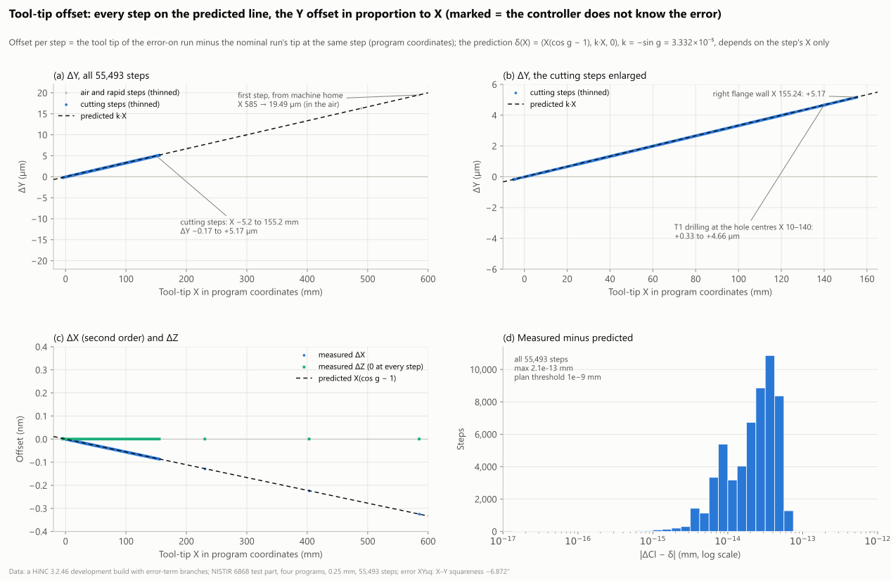
Error terms on, marked: the tool-tip offset of every step (on minus nominal, program coordinates). (a) ΔY against X on all 55,493 steps (steps in the air and rapids thinned out); the first step, at machine zero (program X 585), is 19.49 µm off and cuts nothing. (b) The cutting steps enlarged: −0.17 to +5.17 µm, the largest on the right flange wall at X 155.24. (c) The second-order ΔX (nm) and ΔZ (0 at every step). (d) Measured minus the predicted δ(X): at most 2.1×10⁻¹³ mm, against the plan's threshold of 1×10⁻⁹ mm. Blue = measured, dashed black = predicted. Four programs, 0.25 mm grid; a HiNC 3.2.46 development build with error-term branches.
The part, vertex by vertex
How it is measured: the cut the on run exported (663,473 vertices) is measured vertex by vertex against the nominal cut, giving the signed distance d: positive = material left (blue in the Diff), negative = cut too deep (red). HiNC's Diff gives the pictures and its counters; the deviations in numbers come from this mesh distance.
- All vertices. p01 −4.62 µm and p99 +4.50 µm; the extremes −5.77 and +4.99 µm. The search reads each distance from the triangles of the 12 nearest triangle centroids, so it can only overstate a distance; every vertex it read beyond 6 µm — the same 14 bottom-face vertices as in the control — was rechecked exactly and is 0 (dilemma 6), so no vertex of the on cut lies more than 5.77 µm from the nominal cut. The largest predicted deviation is that of the square's south and north walls at x 150, ∓5.00 µm (k × 150 mm).
- The 812 vertices deeper than −5.05 µm (search readings, not checked exactly) all lie on the R4.7625 surfaces — the squared holes' corners and the drilled walls — and their edges, at x 118.6–141.4: probably the chord height of the grid (dilemma 8). No vertex reads above +5.05 µm.
- Floors and top faces. The floors (z −7, more than 0.3 mm from a wall), 146,446 vertices, and the top faces, 15,330 vertices, are all 0; so are the uncut faces, the plate's bottom and sides.
- Walls predicted at 0 — the squared holes' east and west walls, the square's east and west walls, the flange walls — read within ±0.062 µm: at most 0.061 µm on the square's east wall, four steps of 32-bit coordinates, and 0.046 µm on the squared holes' east and west walls and the flange walls. That is each cut's own rounding to 32-bit coordinates, the floor of this method (dilemma 8).
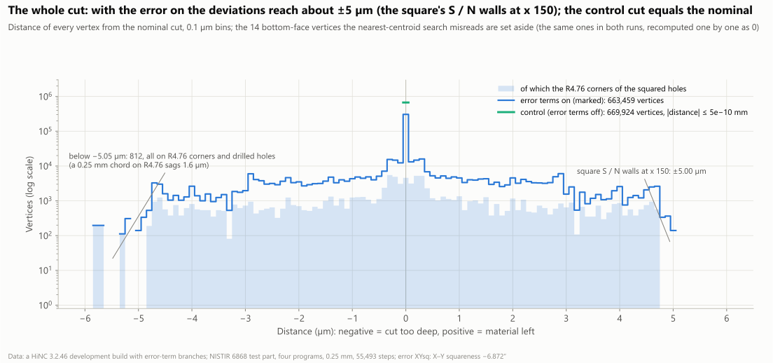
The distance of every vertex of the on and the control cut from the nominal cut (0.1 µm bins, counts on a log scale). The on run spreads over about ±5 µm, with the square's south and north walls at ±5.00 µm at x 150; the 812 vertices below −5.05 µm all sit on R4.76 corners and drilled holes (search readings, not checked exactly; probably the grid's chord height); the light blue marks the squared holes' R4.76 corners among all vertices. The control's 669,924 vertices lie within 5×10⁻¹⁰ mm. The 14 bottom-face artefacts of the search, recomputed exactly as 0, are set aside. Symmetric axis ±6.5 µm. A HiNC 3.2.46 development build with error-term branches.
The squared holes: the pattern moves in +Y, and the two rows read −6.8717″
Each squared hole's centre shift comes from the box means on its four walls: dy = (d_S − d_N)/2 and dx = (d_W − d_E)/2, each box 2 mm along the wall, 1 mm across it and z −6…−1.
- The centre shifts. In all 24 holes dy equals k·x_c within 0.0017 µm, and dx is 0 within 0.0017 µm. Hole 3 (x 10) reads 0.3334 µm against 0.3332 predicted; hole 21 (x 140) 4.6643 µm against 4.6643.
- The orthogonality, by the report's equations 42–44:
- the bottom row 3, 26, 25, 24, 23, 22, 21, fitted as y(x): θ1 = +6.8717″;
- the left column 3–9, fitted as x(y): θ2 = −2.5×10⁻¹²″, that is 0;
- Δθ = θ2 − θ1 = −6.8717″ against −6.8720″ predicted, 0.0003″ apart;
- the opposite corner, the top row 9–15 with the right column 21–15, reads −6.8717″ as well; the 1 mm trimmed runs read −6.8674″.
- The drilled (T1) centres, fitted on the 9.525 mm wall below each squared hole (z −12…−7.5, cut by the drill alone): all 24 move by (0, k·x_c) within 0.0054 µm, and each squared hole's centre lies within 0.0064 µm of its drilled hole's. The report squared the outer holes because “The ‘squared’ outer holes allowed comparison of milled hole centers to the drilled hole centers.” (section 3.2). But the drill and the end mill stop at the same programmed x, and a pure squareness moves both alike: that comparison cannot see the squareness. To read it, fit the two rows of centres as the report does, or measure the walls of the square.
| Distance | Nominal | Measured change | Predicted |
|---|---|---|---|
| 3→9 (left column, along Y) | 130 mm | −0.0011 µm | 0 |
| 9→15 (top row, along X) | 130 mm | −0.0009 µm | 0 |
| 3→21 (bottom row, along X) | 130 mm | −0.0009 µm | 0 |
| 21→15 (right column, along Y) | 130 mm | −0.0010 µm | 0 |
| 3→15 (diagonal) | 183.848 mm | +3.0610 µm | +3.0625 µm |
| 9→21 (the other diagonal) | 183.848 mm | −3.0638 µm | −3.0626 µm |
The two distances along X do not change: every hole moves only in Y, by an amount that grows with x, which changes their length only to second order. Along Y both ends move by the same amount, so those distances do not change either. One diagonal grows and the other shrinks: a parallelogram.
The centre shifts of the 24 squared holes (µm)
| Hole | Centre (x, y), mm | dy measured | k·x_c predicted | Difference | dx measured | Drilled centre dy | Squared minus drilled (dx, dy) |
|---|---|---|---|---|---|---|---|
| 3 | (10, 10) | +0.3334 | +0.3332 | +0.0003 | +0.0002 | +0.3335 | (+0.0001, 0.0000) |
| 26 | (28, 10) | +0.9329 | +0.9329 | 0.0000 | +0.0003 | +0.9336 | (+0.0005, −0.0007) |
| 25 | (43, 10) | +1.4326 | +1.4326 | 0.0000 | +0.0004 | +1.4336 | (+0.0005, −0.0010) |
| 24 | (68, 10) | +2.2656 | +2.2655 | +0.0001 | −0.0013 | +2.2673 | (−0.0017, −0.0017) |
| 23 | (92, 10) | +3.0652 | +3.0651 | +0.0001 | −0.0017 | +3.0675 | (−0.0016, −0.0023) |
| 22 | (120, 10) | +3.9980 | +3.9980 | 0.0000 | −0.0017 | +4.0010 | (−0.0017, −0.0030) |
| 21 | (140, 10) | +4.6643 | +4.6643 | 0.0000 | −0.0008 | +4.6688 | (−0.0008, −0.0046) |
| 20 | (140, 28) | +4.6646 | +4.6643 | +0.0003 | −0.0008 | +4.6688 | (−0.0008, −0.0041) |
| 19 | (140, 43) | +4.6647 | +4.6643 | +0.0004 | −0.0008 | +4.6687 | (−0.0008, −0.0039) |
| 18 | (140, 68) | +4.6633 | +4.6643 | −0.0010 | −0.0008 | +4.6696 | (−0.0007, −0.0063) |
| 17 | (140, 92) | +4.6633 | +4.6643 | −0.0010 | −0.0008 | +4.6693 | (−0.0007, −0.0061) |
| 16 | (140, 120) | +4.6633 | +4.6643 | −0.0010 | −0.0008 | +4.6693 | (−0.0007, −0.0061) |
| 15 | (140, 140) | +4.6633 | +4.6643 | −0.0010 | −0.0008 | +4.6690 | (−0.0007, −0.0058) |
| 14 | (120, 140) | +3.9987 | +3.9980 | +0.0007 | −0.0017 | +4.0010 | (−0.0017, −0.0023) |
| 13 | (92, 140) | +3.0636 | +3.0651 | −0.0015 | −0.0017 | +3.0679 | (−0.0016, −0.0043) |
| 12 | (68, 140) | +2.2642 | +2.2655 | −0.0013 | −0.0013 | +2.2672 | (−0.0017, −0.0030) |
| 11 | (43, 140) | +1.4309 | +1.4326 | −0.0017 | +0.0004 | +1.4340 | (+0.0005, −0.0031) |
| 10 | (28, 140) | +0.9342 | +0.9329 | +0.0013 | +0.0003 | +0.9331 | (+0.0005, +0.0011) |
| 9 | (10, 140) | +0.3323 | +0.3332 | −0.0009 | +0.0002 | +0.3338 | (+0.0001, −0.0015) |
| 8 | (10, 120) | +0.3344 | +0.3332 | +0.0013 | +0.0002 | +0.3333 | (+0.0001, +0.0011) |
| 7 | (10, 92) | +0.3344 | +0.3332 | +0.0013 | +0.0002 | +0.3333 | (+0.0001, +0.0011) |
| 6 | (10, 68) | +0.3329 | +0.3332 | −0.0002 | +0.0002 | +0.3338 | (+0.0001, −0.0008) |
| 5 | (10, 43) | +0.3325 | +0.3332 | −0.0006 | +0.0002 | +0.3336 | (+0.0001, −0.0011) |
| 4 | (10, 28) | +0.3332 | +0.3332 | 0.0000 | +0.0002 | +0.3335 | (+0.0001, −0.0003) |
The script that judged criterion 9 used the 14 holes that carry feature boxes: the bottom row 3, 26, 25, 24, 23, 22, 21, the left column 4–9 and hole 15. The drilled centres' dx all lie within ±0.0005 µm and are not listed.
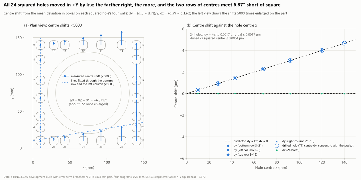
The centre shifts of the 24 squared holes (error terms on, marked). Left: plan view, the shifts drawn 5,000 times enlarged as arrows; the lines fitted through the bottom row and the left column (enlarged alike) meet at Δθ = −6.8717″. Right: dy and dx against the hole centre x; dy follows the prediction k·x (dashed black), dx is 0, and the drilled (T1) centres are concentric with the squared holes. Symmetric axis ±6 µm. 0.25 mm grid; a HiNC 3.2.46 development build with error-term branches.
The 150 mm square: a parallelogram 6.87″ out of square
- The south wall (facing −Y): the tool, offset in +Y, cuts into the square, more so as x grows. The fitted slope is −0.03334 µm/mm (predicted −0.03332), that is 6.878″: −0.03 µm in the bin x 0–2 and −4.96 µm in the bin x 148–150.
- The north wall (facing +Y): the same offset leaves material, at a slope of +0.03332 µm/mm (6.873″), +4.95 µm in the bin x 148–150.
- The west and east walls: 0. Their fitted slopes are within 3×10⁻⁵ µm/mm, the readings within ±0.062 µm (at most 0.061 µm on the east wall).
- The south and north walls rise together toward +X and stay parallel, while the east and west walls stay put: the square's lower-left and upper-right corners close by 6.87″, the other two open by 6.87″.
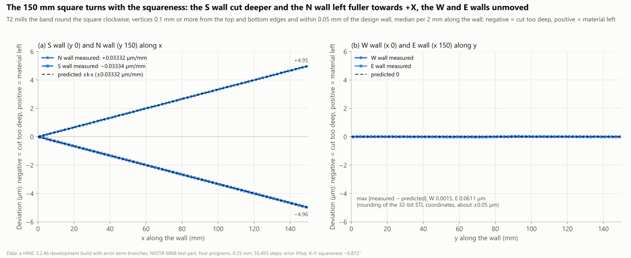
The deviation along the four walls of the 150 mm square (error terms on, marked; median per 2 mm bin). (a) South wall −k·x, north wall +k·x: measured slopes −0.03334 / +0.03332 µm/mm (predicted ∓0.03332), −4.96 / +4.95 µm in the bin x 148–150. (b) West and east walls 0. Symmetric axis ±6 µm, negative = cut too deep, positive = material left. 0.25 mm grid; a HiNC 3.2.46 development build with error-term branches.
The slot: a 2.50 µm shift plus an ellipse of 1.64 / 1.69 µm
Each wall's vertices at z −6…−1 within 0.3 mm of the design radius (29,946 on the inner wall, 37,254 on the outer) are fitted against the azimuth φ about (75, 75) as d = a0 + a1 cos φ + b1 sin φ + a2 cos 2φ + b2 sin 2φ. b1 is the whole ring's shift in +Y and b2 the ellipse; the simulated roundness is the peak-to-valley once the first harmonic is taken out, 2√(a2² + b2²).
| Coefficient, µm | Inner wall, measured | Inner, cutter-centre radius 49.2625 mm | Inner, the plan (wall radius 44.5 mm) | Outer wall, measured | Outer, cutter-centre radius 50.7375 mm | Outer, the plan (wall radius 55.5 mm) |
|---|---|---|---|---|---|---|
| a0 | +0.0031 | 0 | 0 | −0.0023 | 0 | 0 |
| a1 | +0.0022 | 0 | 0 | −0.0008 | 0 | 0 |
| b1 | +2.4972 | +2.4987 | +2.4987 | −2.4987 | −2.4987 | −2.4987 |
| a2 | −0.0005 | 0 | 0 | +0.0021 | 0 | 0 |
| b2 | +0.8199 | +0.8206 | +0.7413 | −0.8453 | −0.8452 | −0.9245 |
| Simulated roundness | 1.6398 | 1.6412 | 1.4826 | 1.6906 | 1.6904 | 1.8491 |
| Fit residual, p01–p99 half-width | 0.056 | 0.060 |
- Why the cutter-centre radius. The tip's offset depends only on the cutter centre's x. The point of
the wall at azimuth φ is cut when the cutter centre stands at the same azimuth on its circle of radius
R_c, where x = 75 + R_c cos φ; so d(φ) = ±k(75 + R_c cos φ) sin φ, which gives b1 = ±75k = ±2.4987 µm,
b2 = ±k·R_c/2 and a roundness of k·R_c. For the inner edge the cutter centre runs 4.7625 mm outside the
wall (R_c 49.2625), for the outer edge inside it (R_c 50.7375); the radii are the program's
(
nist-t2-slot.nc, I−49.2625 and I−50.7375). So the inner ellipse is larger than the plan's and the outer one smaller, and the two come out nearly the same size. - Measured against the cutter-centre prediction: b2 0.0007 / 0.0001 µm apart, the roundness 0.0014 / 0.0002 µm. The 1 mm trimmed runs read b2 +0.8194 / −0.8456 µm.
- The grid reads the ellipse. A 0.25 mm cell is about 150 times as wide as the ellipse, yet the residual after the fit has a p01–p99 half-width of only 0.056 / 0.060 µm.
- Where the inner pass starts and ends: within 1° of φ 0 on the inner wall (243 vertices) the distance averages +0.079 µm and reaches +0.368 µm (not checked exactly), where the prediction is almost 0 (dilemma 7).
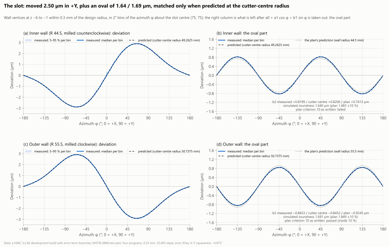
The slot's inner wall (top) and outer wall (bottom) against the azimuth φ: the deviation on the left (median and 5–95 % per 2° bin), and on the right the oval part left once the first harmonic is taken out. Blue = measured, dashed black = the prediction at the cutter-centre radii 49.2625 / 50.7375 mm, dotted grey = the plan's prediction at the wall radii 44.5 / 55.5 mm. b2 measured +0.8199 / −0.8453 µm, the cutter-centre prediction +0.8206 / −0.8452, the plan +0.7413 / −0.9245; as written, criterion 10 fails on the inner wall and passes on the outer. Symmetric axes. 0.25 mm grid; a HiNC 3.2.46 development build with error-term branches.
The 84 feature boxes
The plan set 84 boxes on the part, each with a predicted value: the four walls of 14 squared holes (56), the slot's inner and outer walls at eight azimuths each (16), two places on each wall of the square (8), and four faces that must not move — the flange top, the top of the slot's island, the band floor and the slot floor. Each box compares the signed mean of the vertices in it with the prediction.
| Group | Boxes | Largest measured − predicted, absolute | Tolerance |
|---|---|---|---|
| Squared holes, south and north walls | 28 | 0.0036 µm (hole15-S) | 0.3–0.70 µm |
| Squared holes, east and west walls | 28 | 0.0067 µm (hole21-W, hole15-W) | 0.3 µm |
| Square, south and north walls | 4 | 0.0066 µm (square-N-x25) | 0.3–0.62 µm |
| Square, east and west walls | 4 | 0.0023 µm (square-E-y125) | 0.3 µm |
| Slot | 16 | 0.101 µm against the plan (slot-in-000); against the cutter-centre prediction within 0.038 µm except slot-in-000 | 0.3–0.40 µm |
| Faces that must not move | 4 | 0 at every vertex | 0.05 µm at every vertex |
The slot boxes at 45°, 135°, 225° and 315° read about 0.08 µm off the plan: the plan's radius error (dilemma 5), still inside the tolerance. Against the cutter-centre prediction, every slot box but slot-in-000 lies within 0.038 µm.
The 16 slot boxes (µm)
| Box | Vertices | Measured mean | The plan (wall radius) | Measured − plan | Cutter-centre prediction | Measured − cutter-centre prediction | Tolerance |
|---|---|---|---|---|---|---|---|
| slot-in-000 | 147 | +0.101 | 0.000 | +0.101 | 0.000 | +0.101 | 0.300 |
| slot-out-000 | 105 | +0.006 | 0.000 | +0.006 | 0.000 | +0.006 | 0.300 |
| slot-in-045 | 210 | +2.589 | +2.508 | +0.081 | +2.587 | +0.002 | 0.376 |
| slot-out-045 | 210 | −2.610 | −2.691 | +0.082 | −2.612 | +0.002 | 0.404 |
| slot-in-090 | 147 | +2.489 | +2.499 | −0.009 | +2.499 | −0.009 | 0.375 |
| slot-out-090 | 147 | −2.536 | −2.499 | −0.038 | −2.499 | −0.038 | 0.375 |
| slot-in-135 | 210 | +0.949 | +1.026 | −0.076 | +0.946 | +0.003 | 0.300 |
| slot-out-135 | 210 | −0.921 | −0.842 | −0.079 | −0.922 | +0.001 | 0.300 |
| slot-in-180 | 147 | 0.000 | 0.000 | 0.000 | 0.000 | 0.000 | 0.300 |
| slot-out-180 | 105 | 0.000 | 0.000 | 0.000 | 0.000 | 0.000 | 0.300 |
| slot-in-225 | 210 | −0.945 | −1.026 | +0.081 | −0.946 | +0.002 | 0.300 |
| slot-out-225 | 210 | +0.919 | +0.842 | +0.076 | +0.922 | −0.003 | 0.300 |
| slot-in-270 | 105 | −2.499 | −2.499 | −0.001 | −2.499 | −0.001 | 0.375 |
| slot-out-270 | 105 | +2.499 | +2.499 | 0.000 | +2.499 | 0.000 | 0.375 |
| slot-in-315 | 210 | −2.584 | −2.508 | −0.076 | −2.587 | +0.003 | 0.376 |
| slot-out-315 | 210 | +2.605 | +2.691 | −0.087 | +2.612 | −0.007 | 0.404 |
slot-out-090's −0.038 µm against the cutter-centre prediction is the discretization of one mesh against another on a curved surface, inside the tolerance, and was not followed further.
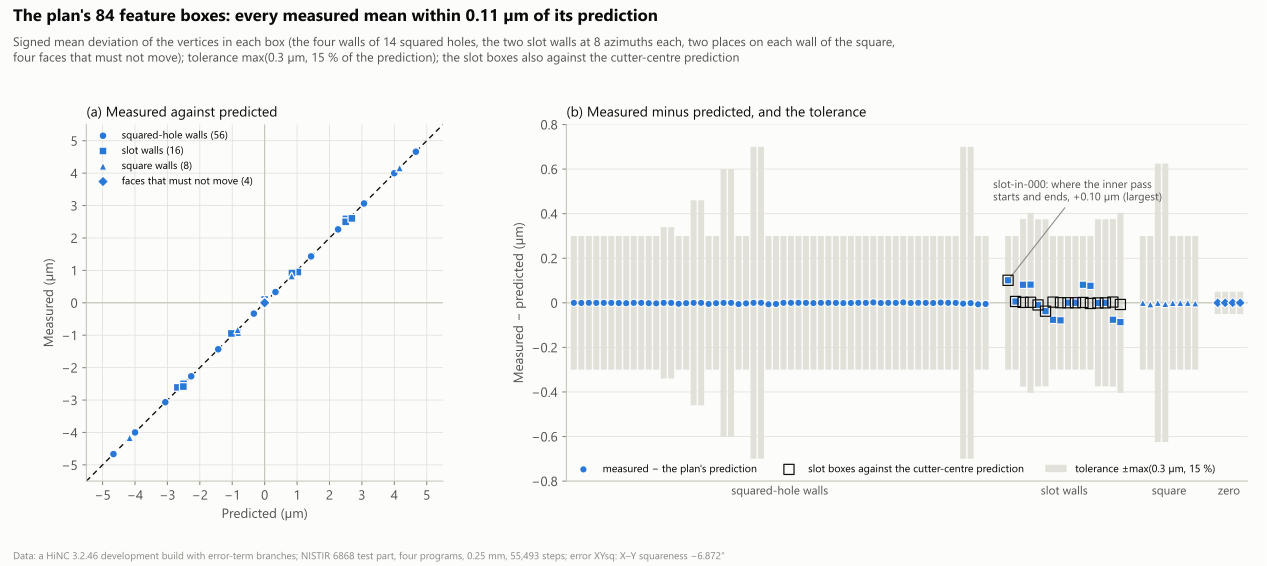
The plan's 84 feature boxes (error terms on, marked). (a) The measured mean against the prediction; the diagonal is equality. (b) Measured minus predicted, with each box's tolerance, max(0.3 µm, 15 %); the slot boxes are also drawn in black squares against the cutter-centre prediction. The largest difference is 0.101 µm, at slot-in-000, where the inner pass starts and ends. Symmetric axes. 0.25 mm grid; a HiNC 3.2.46 development build with error-term branches.
Marked and unmarked (1 mm)
These four are plain three-axis G54/G43 programs: no RTCP, no tilted plane, no CL. The controller turns them into machine coordinates from the program, the work offset and the tool length alone and has no use for the kinematic chain, so whether it knows the squareness or not, it computes the same machine coordinates, and the error is cut into the part the same way (what a mark changes). The same batch's RPTU part 8 case only stated this reasoning; the roundness test part case and this one played the unmarked run, at 1 mm:
- Unmarked minus marked: tool tip 0 and machine coordinates 0 on all 55,493 steps; the series are bit-identical, the touch flag included.
- Both runs' machine coordinates equal the nominal's; both runs' tips are off by −0.17 to +19.49 µm, as the formula says.
- The two cuts have all 54,834 vertices identical, and the two runs'
Diff--Statsare identical too.
The one difference is P0: with the mark cleared, it reads 15.19 µm off (dilemma 4). A touch-off on the real machine, on the part, has no such offset, so the unmarked run also typed in the G54 a touch-off finds. How much a controller that knows the error could take back shows only under RTCP, a tilted plane or CL playback, which this case cannot show.
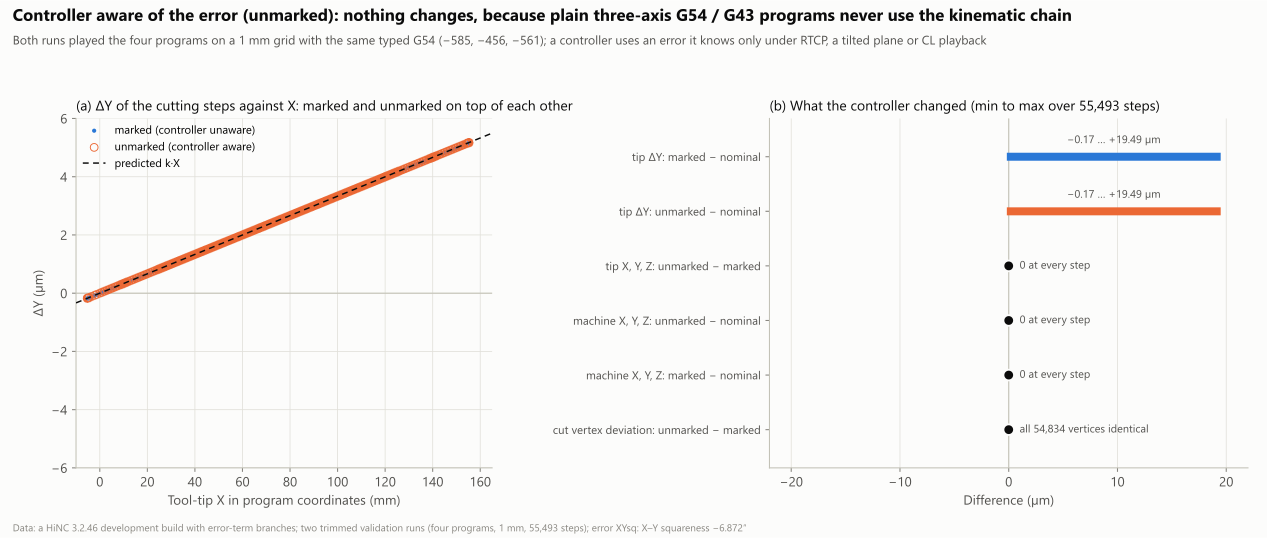
The marked and the unmarked run of the trimmed validation (1 mm). (a) ΔY of the cutting steps against X: the two runs lie on top of each other on the prediction k·X. (b) What the controller changed, as the range over the 55,493 steps: both runs' tip ΔY −0.17 to +19.49 µm; the tip of unmarked minus marked and both runs' machine coordinates against the nominal 0 at every step; the two cuts' 54,834 vertices identical. Both runs typed in the same G54, (−585, −456, −561). A HiNC 3.2.46 development build with error-term branches.
The control run and the Diff on the part
The control run (switch off, with a Diff) is the nominal run played again: its per-step series equals the nominal's bit for bit, tips and machine coordinates 0 apart. Its cut has the nominal's vertices: of 669,938, 669,924 lie within 5.0×10⁻¹⁰ mm, 36.5 % of them at exactly 0; the other 14 are artefacts of the search and recompute exactly as 0 (dilemma 6).
The pictures below alternate in place between the run with the error terms on (marked) and the control run (off), 0.9 s per frame, written at full size. Each frame was taken by putting the run's recorded stock back on the canvas with its Diff, not by replaying. The cameras are HiNC's front and back views raised and moved closer, and its default isometric view moved closer. The canvas carries no interface text, so the English and Chinese captures are the same pictures pixel for pixel; only the frame labels differ.
The Diff from above the front (the −Y side), looking +Y, alternating in place. In the “on” frame the walls facing south — the square's south wall and the north wall of every squared hole — run from green on the left (small x) to orange on the right (large x): cut too deep, about −4.7 to −5.0 µm at x 140–150. The left column of holes is all light green (−0.33 µm); the slot's far outer wall and near inner wall are yellowish (about −2.5 µm). The “off” frame is all green. Diff colour scale ±0.006 mm (red = cut too deep, blue = material left, green = 0, both signs alike); 0.25 mm grid; a HiNC 3.2.46 development build with error-term branches.
From above the back (the +Y side), looking −Y, so +X is on the left of the picture; alternating in place. In the “on” frame the walls facing north — the square's north wall and the south wall of every squared hole — run from green on the right (small x) to blue on the left (large x): material left, up to about +5 µm. The slot's far outer wall (φ 270°) and near inner wall (φ 90°) are cyan (about +2.5 µm). The “off” frame is all green. Scale, grid and build as above.
The whole part seen obliquely from above the south-west (the −X, −Y side), alternating in place. In the “on” frame the square's south wall and the north walls of the squared holes turn orange-brown toward +X (cut too deep); the walls facing ±X, the floors and the top faces stay green. The “off” frame is all green. Scale, grid and build as above.
Diff--Stats of the five runs with a Diff
| Run | Reported leaves | Surface leaves before comparison | Expanded on demand | New nodes | NaN leaves | Measured wires | Unmeasured wires | Target triangles |
|---|---|---|---|---|---|---|---|---|
| t-on | 56,956 | 53,719 | 1,375 | 4,612 | 17 | 212,399 | 2,217 | 106,691 |
| t-control | 57,139 | 54,664 | 1,121 | 3,596 | 0 | 213,858 | 268 | 106,691 |
| t-unmarked | 56,956 | 53,719 | 1,375 | 4,612 | 17 | 212,399 | 2,217 | 106,691 |
| f-control | 707,696 | 682,044 | 11,630 | 37,282 | 0 | 2,695,142 | 1,774 | 1,325,472 |
| f-on | 688,404 | 657,741 | 13,363 | 44,026 | 44 | 2,684,991 | 3,217 | 1,325,472 |
The nominal runs make no Diff. The target triangles are fewer than the exported STL holds: 1,325,472 against 1,346,250 at 0.25 mm (20,778 fewer) and 106,691 against 107,570 at 1 mm (879 fewer); this was not followed up, and triangles of zero area are one possible cause. NaN leaves appear only in the runs whose cut differs from the nominal (44 in f-on, 0.0064 % of the reported leaves; 17 each in t-on and t-unmarked) and none in the control runs; what they are was not followed up.
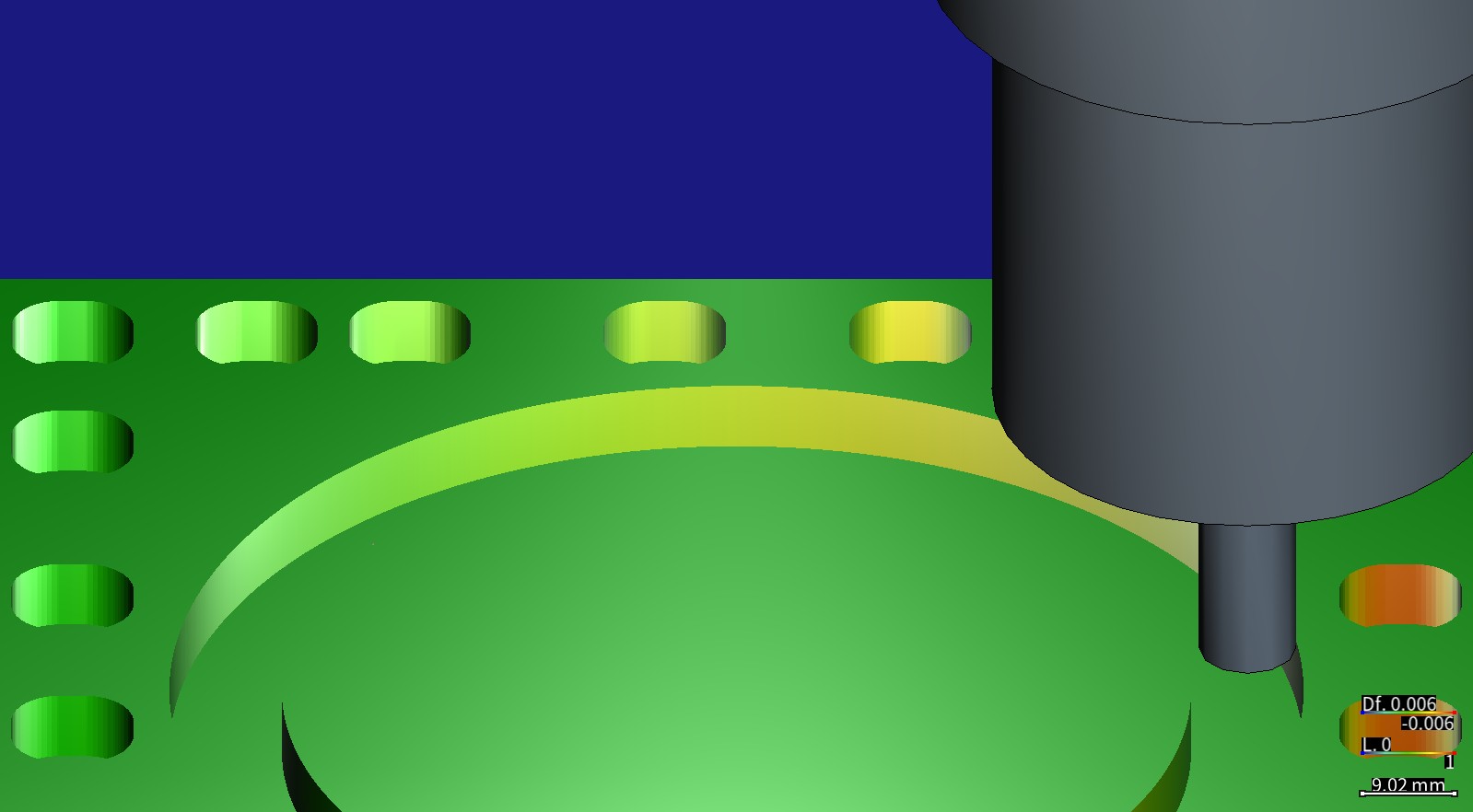
A close-up of the same parked pose: T2's shank and the nose of the ER32 collet chuck above the slot's outer wall. On the left, the north walls of the top-row squared holes run from green to yellow; on the right, the squared hole at x 140 is orange. T2 sticks out 30 mm and the features are at most 7 mm deep, so while cutting the holder's nose stays 23 mm above the stock (criterion 11). Diff colour scale ±0.006 mm (red = cut too deep, blue = material left, green = 0); 0.25 mm grid; a HiNC 3.2.46 development build with error-term branches.
Against the report
| This simulation (the X–Y squareness alone) | The report's model (every error the LBB measured) | The report's CMM (21 parts) | |
|---|---|---|---|
| Orthogonality Δθ | −6.8717″ (α put in: −6.872″) | −5.10″ (Table 5, analytic, standard uncertainty 11.09″); −4.68″ (Table 6, Monte Carlo, 11.03″) | −1.059″ (Table 14; pooled standard deviation between parts 8.96″; expanded uncertainty of a future estimate 18.10″) |
| Slot roundness, inner / outer edge | 1.640 / 1.691 µm | 17.9 / 18.0 µm (Tables 7 and 8, standard uncertainty 3.1 µm) | 20.99 / 26.02 µm (Tables 15 and 16, expanded uncertainty 5.49 / 12.09 µm) |
| Milled-hole distance 3→9 | −0.001 µm | −2 µm (Table 17) | 0.00 µm (Table 13, uncertainty 18.86 µm) |
| Milled-hole distance 9→15 | −0.001 µm | −3 µm | −11.16 µm (18.99 µm) |
| Milled-hole distance 3→15 | +3.061 µm | −1.8 µm | −5.40 µm (19.84 µm) |
- The orthogonality. The simulated part's orthogonality is the squareness put in, 0.0003″ apart.
That does not validate the report; it isolates one error the report measured and shows how much of the
measured result it makes.
- It lies 5.81″ from the CMM mean, 3.66 µm over 130 mm, which is 0.32 times the expanded uncertainty of 18.1″: within the uncertainty, not a match.
- The report's model, −5.10 / −4.68″, also carries straightness and yaw; the plan estimated that the linear part of the straightness alone makes an effective squareness of about −5.3″. The report's own conclusion: “In this case the model estimates over-predicted the orthogonality error but did produce the same direction of error.” (section 6.3)
- Describing the CMM's computation, section 5.3 says the vertical row's slope “had to be reversed and then it could be added to the horizontal slope”: read literally, θ2 + θ1, with θ1's sign opposite to equation 44's θ2 − θ1. Section 6.3 compares the CMM's −1.06″ directly with the model's −4.89″ and calls the direction the same; this page compares the same way. Here θ2 = 0; read by section 5.3 literally, the part would be +6.87″, 7.93″ from the CMM's −1.06″, 0.44 times the expanded uncertainty, and the conclusion would not change.
- The roundness. The squareness alone gives 1.64 / 1.69 µm, 7.8 / 6.5 % of the CMM's values and
9.2 / 9.4 % of the report's model: under a tenth.
- The two definitions also differ. Here the roundness is the second harmonic's peak-to-valley; the report's is the largest minus the smallest radius about the best-fit circle. The CMM measured 37 points; the model, at 36 points, added each error's value and its uncertainty times random numbers over 1,000 Monte Carlo trials (section 4.6, equation 46). So only the sizes compare.
- On the CMM's roundness, section 5.4 notes that the inner and the outer edge were cut in opposite directions: “Direction of cut may have had an effect in leaving small debris.”
- The hole distances. The squareness changes only the diagonal (+3.06 µm); the distances along X and along Y stay. The CMM's 9→15, −11.16 µm, runs along X: the X scale error (Table 2 slope −1.89×10⁻⁵) alone would shorten it by 2.46 µm, and the report's model gives negative values on all three distances (−2, −3 and −1.8 µm). Heat and the other errors are not in this model. All three lie within the uncertainty of about 19 µm, which the report notes is not an expanded uncertainty for Table 13.
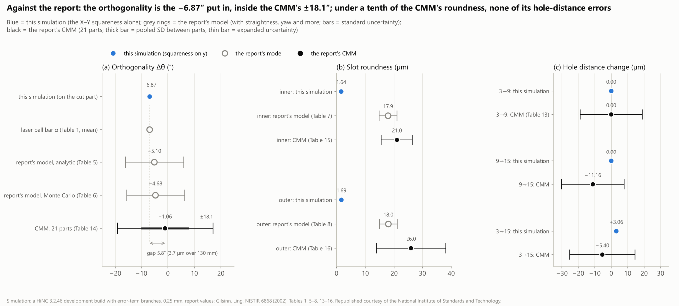
This simulation against NISTIR 6868. Blue = this simulation (the X–Y squareness alone); grey rings = the report's model (bars = standard uncertainty); black = the report's CMM (21 parts; thick bar = pooled standard deviation between parts, thin bar = expanded uncertainty). (a) Orthogonality: 5.8″ from the CMM mean (3.7 µm over 130 mm), inside ±18.1″. (b) Slot roundness. (c) Change of the milled-hole distances. Simulation: a HiNC 3.2.46 development build with error-term branches, 0.25 mm grid. Report values: Gilsinn, Ling, NISTIR 6868 (2002), Tables 1, 5–8 and 13–16. Republished courtesy of the National Institute of Standards and Technology.
What the runs cost
All runs used a private instance of a HiNC 3.2.46 development build with error-term branches on a shared 32-thread server, with physics off and collision detection on. The instance was restarted before every run, so the peak memory (VmHWM) is that run's own.
| Run | Grid | Steps | Wall clock | Peak memory (VmHWM) |
|---|---|---|---|---|
| t-nominal | 1 mm | 55,493 | 30.0 s | 0.632 GB (0.589 GiB) |
| t-on | 1 mm | 55,493 | 30.0 s | 0.723 GB (0.673 GiB) |
| t-control | 1 mm | 55,493 | 30.0 s | 0.725 GB (0.675 GiB) |
| t-unmarked | 1 mm | 55,493 | 30.0 s | 0.720 GB (0.671 GiB) |
| f-nominal | 0.25 mm | 55,493 | 100.1 s | 1.968 GB (1.833 GiB) |
| f-control | 0.25 mm | 55,493 | 100.1 s | 2.975 GB (2.771 GiB) |
| f-on | 0.25 mm | 55,493 | 100.1 s | 2.984 GB (2.779 GiB) |
- The wall clock runs from the start of the play to the poll that reads
Finished; the poll comes every 5 s, so 100.1 s means the play ended between 95 and 100 s, and 30.0 s between 25 and 30 s. - The seven wall clocks add up to 420.3 s, about 7 minutes. The four programs' simulated machining time is 442 s, and at 0.25 mm the whole part plays in about 100 s.
- The two runs with a Diff took about 0.94 GiB more than the nominal run (0.938 and 0.946 GiB).
- The plan's estimate was 30–40 s and under 2 GB for a trimmed run, at most 5 minutes and 10 GB for a whole-part run, with a stop at a peak of 24 GB to fall back to 0.5 mm. Every run stayed inside the estimate, and the stop was never reached.
- Whether other work that takes no lock ran on the server at the same time is not in the records, so a wall clock may include that load.
What it brings
- For a machining engineer.
- An X–Y squareness of −6.87″ on a production three-axis machine, 33 µm per metre, cuts at most about 5 µm into this 150 mm test part: the square's south wall 4.96 µm too deep near x 150, its north wall 4.95 µm left there.
- A squareness's effect is the angle times the X travel a feature spans, counted from the touch-off point: the bottom row's centres move from 0.33 to 4.66 µm, the left column's all by 0.33 µm.
- The squared and the drilled holes move together, so the concentricity of a drilled hole to a milled one cannot show a squareness; fit two rows of centres, or measure the walls of a square.
- In plain three-axis programs like these, the squareness is cut into the part whether the controller knows it or not.
- In HiNC, a constant error measured on a machine can be put into the model to see its shape and size on one's own part before the part is cut.
- For a teacher or a student.
- How the tip offset follows from the machine chain: a rotation about Z upstream of Y is, seen on the part, an X travel that leans.
- How the report defines the orthogonality (equations 42–44), how the two rows of centres read 6.87″ back, and why 6.87″ is only 5 µm over 150 mm.
- Why the slot comes out as a shift plus an ellipse, and why the ellipse takes the cutter-centre radius, not the wall radius.
- Why the simulated roundness is under a tenth of the CMM's: a real part also carries scale errors, straightness, heat, the cutting and the measuring.
- For someone weighing the approach.
- From a scanned PDF of 2002 to a base project, an error-term project and seven plays in one day; the seven plays took 420 s of server time in all, at most 2.99 GB each.
- The formula and the predictions were written before the first play: the tip met the exact formula within 2.07×10⁻¹³ mm; the hole centres, the orthogonality and the distances met theirs to 0.002 µm and 0.0003″, and the box means on the square's walls to 0.007 µm.
- What the prediction missed is written as it is: criterion 10 failed as written on the inner wall, because the plan used the wrong radius.
- Against the report, the result is “within the uncertainty”, never “a match”.
Honest limits
- One error, and a constant one. The report's model also has X and Y scale errors (Table 2 slopes −1.89×10⁻⁵ and −1.823×10⁻⁵), straightness and yaw; they vary with position, are no fixed rigid transform, and an error term cannot hold them (see Machine Geometric Error). Heat, cutting forces, clamping, burrs and debris are not in the model either. So the case shows what this one error alone cuts, not a reproduction of the 21 parts.
- The machine is not the report's. The skeleton borrows only the report's travels and this one angle; it carries Y on X where the report's machine carries X on Y, and the angle between the two motions is the same.
- The part is rebuilt. The plate, the band and the drilled depth were measured on a stretched scan, and the four small bosses were left out; tools, holder, material, fixture and programs are chosen.
- Geometry only. Physics is off: no cutting force, no deflection, no temperature.
- Plain three-axis programs: marked or not, the same part. How much a controller that knows the error could take back shows only under RTCP, a tilted plane or CL playback, which this case cannot show.
- The comparison with the report goes to size and direction only. The two roundness definitions differ; and the CMM computation of section 5.3, read literally as θ2 + θ1, has θ1's sign opposite to equation 44's. This page compares as section 6.3 does; read literally, the part would be +6.87″, 7.93″ from the CMM, still within its uncertainty.
- The mesh distance has a floor (dilemma 8). On the 1 mm trimmed mesh, 198 vertices off the bottom face differ by more than 10 µm: 182 at −17.5 to −21.6 µm where the squared holes' straight walls meet their corners (x 66.7–141.4), and 16 at +0.41 and +0.45 mm — exactly 1/√6 and 1/√5 mm — where the right flange wall meets the plate's front and back edges. Rechecked exactly against the triangles of the 1 mm nominal cut, all 198 are real differences between the two 1 mm cuts, not artefacts of the search; what makes the 16 at the flange corners was not investigated. The part is judged on the 0.25 mm runs only.
- Observations not followed up. The touch flag differs between the on and the nominal run on a few
steps: 2 at 0.25 mm, at the closing points φ 0 of the slot's two circles (
nist-t2-slot.nclines 19 and 22, one each way), and 17 at 1 mm, at the closing segments of 17 squared-hole paths; a path moved by a few micrometres is enough to change the flag of a step that just grazes the edge of a cell, and no criterion uses the flag. The Diff's target triangles are fewer than the STL's, and NaN leaves appear only in the runs whose cut differs from the nominal (see the Diff–Stats above). The inner wall's +0.37 µm at φ 0 is unexplained (dilemma 7). - The work offset of the error-term runs is typed in, as a touch-off would find it; HiNC's P0 measures differently (dilemma 4).
- The wall clock is a multiple of the polling interval, 5 s.
What a reader can take to their own case
- Derive the sign of an error from the source's own definitions, and confirm the reading by recomputing a number the source prints, as Table 5's −5.10″ confirmed it here.
- Put the pivot of an error at the touch-off pose: then the work offset a touch-off finds does not move, and nothing has to be typed differently between the runs.
- Predict a contoured wall from the cutter centre's path: the slot's ellipse is k × the cutter-centre radius, not k × the wall radius.
- Read a squareness from two rows of features or the walls of a square, not from a drilled hole against a milled one at the same programmed position.
- In a plain three-axis program, marking does not matter for the cut; only RTCP, a tilted plane or CL playback lets the controller compensate (see what a mark changes).
- Judge a criterion as written: a corrected prediction is a finding about the plan, never a new verdict.
- Check extreme mesh distances exactly before reading them as shape, and know the method's floor: the chord height on small radii and 32-bit coordinates.
- Compare one modelled error with measured parts in size and direction only, inside the measurement's uncertainty: one constant error is not a reproduction of the parts.
Source and licence
Report: David E. Gilsinn (NIST, Mathematical and Computational Sciences Division, Gaithersburg MD) and Alice V. Ling (AFRL/DEX, Kirtland AFB NM), Comparative Statistical Analysis of Test Parts Manufactured in Production Environments, NISTIR 6868, National Institute of Standards and Technology, June 2002 (the authors and affiliations as the title page prints them), https://doi.org/10.6028/NIST.IR.6868; PDF at https://nvlpubs.nist.gov/nistpubs/Legacy/IR/nistir6868.pdf, downloaded on 2026-10-07: 4,840,610 bytes, 100 pages, SHA-256
423534d643f8c80e7a9af5ee84d5378f048606ce5b01cc159d6289f0136c04ab; its metadata reads “Digitized by the Internet Archive”, a scan of the printed report. Search terms if the link moves:NISTIR 6868,Comparative Statistical Analysis of Test Parts Manufactured in Production Environments,Gilsinn Ling laser ball bar test parts CMM.Data set: none. The report prints its measurements in tables (Tables 1–16, Appendices A, B and G); there is no CAD file and no NC program.
Licence: NIST's statement for its Technical Series publications, read on 2026-10-07 at https://www.nist.gov/open/copyright-fair-use-and-licensing-statements-srd-data-software-and-technical-series-publications under the heading “NIST Technical Series Publications”, verbatim:
In accordance with Public Law 100-519, Section 107 (Oct 24, 1988), NIST maintains a research information center to support the research, publishing, and preservation needs required to fulfill the scientific and technical mission of NIST. This includes publishing the NIST Technical Series: technical reports and Journal of Research of NIST. Works authored by NIST employees are not subject to Copyright protection within the United States; foreign rights are reserved. To the extent NIST may assert rights outside of the United States, the public is granted the non-exclusive, perpetual, paid-up, royalty-free, worldwide right to reprint works in all formats including print, electronically, and online, and in all subsequent editions, and derivative works. Please use the recommended citation format below followed by ‘Republished courtesy of the National Institute of Standards and Technology.’ Some works published by NIST may have been written by third parties and may be subject to copyright protection.
The report prints no copyright line. Its first author was at NIST; the second, A. V. Ling, is listed at AFRL/DEX, an Air Force laboratory, and whether that part of the work was written as a federal employee could not be found (a search on 2026-10-07 found nothing either way), so the statement's last sentence may apply to part of the text (dilemma 2). This page therefore relies only on what no licence restricts: the report's numbers and part dimensions, and a few short quotations with their section numbers. No figure, table or page of the report is reproduced; the part is redrawn by us, and every picture is a HiNC render.
Attribution:
Measured data and part dimensions: D. E. Gilsinn, A. V. Ling, “Comparative Statistical Analysis of Test Parts Manufactured in Production Environments”, NISTIR 6868, National Institute of Standards and Technology, Gaithersburg MD (2002), https://doi.org/10.6028/NIST.IR.6868. Republished courtesy of the National Institute of Standards and Technology. Changes: the part model, the NC programs, the tools and the HiNC project are ours, built from the report's drawing and tables (see “What we changed” below).
NIST does not endorse this case, HiNC or any product used here; the material is provided as is, without warranty.
What we changed:
- The part: a script writes it from the drawing and Table A1, the plate as a block of about 196 × 165 × 19 mm and the features as our programs cut them. The plate's size, the band between the square and the two side flanges, and the outer holes' drilled depth were measured on the scanned figure against its labelled dimensions; the four small bosses and their holes are left out.
- The programs (Fanuc) are ours; the slot is milled in the directions of section 5.4, and the depth steps, paths, feeds and speeds are chosen.
- Tools, holder, material and fixture are chosen. Every run is physics off, so none of them changes the geometric errors this case compares.
- The machine is HiNC's shapeless three-axis skeleton
Empty-wXYOZStwith the report's travels. It carries Y on X where the report's model carries X on Y; the angle between the two motions, which is what the part records, is the same either way. - Added for this case: one marked error-term branch on the machine,
XYsq. Its value is read from the report's Table 1 (the mean of five passes), its place upstream of the Y axis follows the owner's ruling, and its sign and pivot are derived.
What we did: every picture is a HiNC capture; the charts draw HiNC's per-step results and cut meshes, and the numbers the report prints (Republished courtesy of the National Institute of Standards and Technology). Everything is simulated: no part was cut, and the report's 21 parts themselves were not used. The reader fetches the report from NIST.
See Also
- Building Virtual Machine Tools: Error terms — where an error term may go, what a mark changes, the switch and work offsets on a machine with error terms
- Kinematic Topology: Error-Term Branches — the model: the controller on the nominal chain, the machine with the errors
- Machining Issues Outside the Model: Machine Geometric Error — the geometric errors an error term cannot hold, such as scale and straightness
- A Roundness Test Part with the Machine's Measured Squareness Errors — another test part built from a paper's numbers, with an X–Y squareness upstream of Y on the same skeleton machine
- RPTU Benchmark Part 8 on a Machine with Three Measured Squareness Errors — three squareness errors on an ISO 10791-7-style test piece, where a boss's two lobes already followed the cutter-centre radius
- The NIST Cone Frustum on a C Axis 10 µm Off Centre — another NIST test part, with a measured rotary-axis error under RTCP
- Geometry Validation — the geometry difference, its detection radius and its colour scale
- Program Zero Alignment — P0, and typing in a measured work offset
- Showcase — the other cases, and how a case page reads