A Roundness Test Part with the Machine's Measured Squareness Errors: Only the X–Y Squareness Makes the Circles Oval
Holub et al. (Applied Sciences 10, 6233, 2020) measured a three-axis vertical machining centre with a laser tracer and switched on its controller's volumetric compensation: the volumetric error fell from 49 µm to 14 µm. They cut the same test part before and after (WP1, WP2), and the roundness of its Ø300 flange, Ø200 boss and Ø100 bore — RONt, the mean of seven measured positions as the paper prints it — only moved from 10.13 / 9.39 / 5.37 µm to 6.16 / 5.71 / 5.59 µm; the bore got slightly worse.
Here an AI agent puts the three constant squareness errors the paper measured into a HiNC machine as error terms: the X–Y squareness E_C0Y of 22.4 µm/m (the ballbar, Table 8) directly upstream of the Y axis, and the squareness of Z to Y and to X, E_A0Z +33 and E_B0Z −56 µrad (the laser tracer, Fig. 6, read off the chart), combined into one 65 µrad rotation directly upstream of the Z axis. The paper publishes no NC and no model, so the part, its stock, three finishing circles and the project are the agent's, built from the paper's numbers. Three plays at a 0.25 mm grid on a HiNC 3.2.46 development build with error-term branches: error terms off (the nominal cut, the ideal geometry of every comparison), off again with a Diff (the control), and on with the controller unaware of them.
- The tool tip follows the prediction to within 1.24×10⁻¹³ mm on every step: δ = A·(X, Y, Z), written down before the first play. The machine coordinates are bit-identical with and without the errors.
- Only the X–Y squareness reaches the roundness. It cuts each circle into an ellipse with its long axis at 135°/315°: simulated RONt 3.535 / 2.421 / 0.940 µm against γ × tool-centre radius 3.539 / 2.419 / 0.941 µm predicted, the same on all seven sections of each diameter.
- The Z squareness leaves the roundness alone and tilts the axis. The three cylinders share one axis tilted by 65 µrad, its sections displaced toward 30.5° the deeper they lie — they stay coaxial — so each wall leans 3.25 µm over 50 mm against the end faces. The lean of the walls rests on the model's assumption that the spindle tilts with Z.
- Against the paper, the constant X–Y squareness explains 35 % / 26 % / 18 % of the RONt measured on WP1; the residual squareness after compensation scales to 0.98 / 0.67 / 0.26 µm, while WP2 still measured 6.16 / 5.71 / 5.59 µm: what the compensation left is mostly not squareness.
Everything here is simulated; no part was cut.
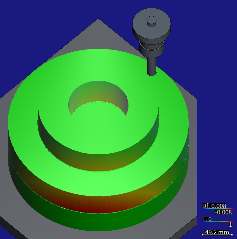
The stock cut with the error terms on (marked) put back on the canvas and the parking program
NC/pose-d200.nc played on it (no cut): T1, a Ø16 four-flute end mill in its ER25/BT40 collet chuck at
70 mm stick-out, parked in the air beside the boss (isometric view). The part shows that run's Diff,
±0.008 mm: red = cut too deep, blue = material left, green = 0, both signs alike. The flange band is
reddest on the −X−Y side nearest the camera; the top faces were not cut and stay green. A HiNC 3.2.46
development build with error-term branches, 0.25 mm.
| Measured on a HiNC 3.2.46 development build with error-term branches, 0.25 mm, error terms on against off | Ø300 flange | Ø200 boss | Ø100 bore |
|---|---|---|---|
| Two-lobe term b2, mean of 7 sections (predicted −s·γR_c/2) | −1.767 (−1.770) µm | −1.211 (−1.210) µm | +0.470 (+0.470) µm |
| Simulated RONt, mean of 7 sections (predicted γR_c) | 3.535 (3.539) µm | 2.421 (2.419) µm | 0.940 (0.941) µm |
| RONt measured on WP1 by the paper, mean of 7 positions | 10.13 µm | 9.39 µm | 5.37 µm |
| Slope of the section centre shift against depth (predicted 65.00 µrad) | 65.10 µrad | 64.94 µrad | 65.02 µrad |
| Wall lean against the end face over 50 mm (predicted 3.25 µm) | 3.255 µm | 3.247 µm | 3.251 µm |
The case
The paper (source and licence below) is the only file the source publishes: no CAD model, no NC program, no data set; every number is printed in the PDF. HiNC's public page Machining Issues Outside the Model already cites its numbers for the gap between volumetric error and a part's roundness. What the agent was given:
- The test part (Fig. 3a): a Ø300 × 100 mm flange, a Ø200 × 50 mm boss on it and a central Ø100 bore 60 mm deep. Each diameter was measured at seven positions 5 mm apart; position 04 is the representative one (Fig. 11).
- The cutting data (Table 2): 200 m/min, 0.1 mm per tooth, a Ø16 four-flute solid carbide end mill in an ISO40 ER25 holder; the material EN AW-2007.
- The machine (Section 2.2, Table 1): a KOVOSVIT MAS MCV 754 QUICK three-axis vertical machining centre with a Sinumerik 840D sl and the VCS A3 option; travels X 754, Y 500, Z 550 mm.
- The measurements: the ballbar squareness (Tables 8–10) 22.4 / 10.5 / 13.8 µm/m on the Ø300 / Ø200 / Ø100 circles before compensation and −6.2 / −6.3 / +4.8 µm/m after; the laser tracer's 19 error components (Fig. 6) drawn as bars without printed values, volumetric error 49 → 14 µm (Fig. 7); the RONt of WP1 and WP2 at every position (Tables 11–13), measured on a Talyrond 595S.
- The paper's conclusion (Section 5): the circularity error is “significantly affected by the squareness error of two relative axes in the machining plane”.
- The request: showcases of HiNC's error-term branches, built on cases that exist, paper cases welcome; the owner's ruling that an error goes only directly upstream of an axis or the spindle, one marked static branch each.
What nothing states:
- The NC, the stock, the fixture, where the part sits. The paper names the finishing only as “outside milling technology” for Ø300 and Ø200 and “another type of machining technology” for the bore.
- The Z squareness values. Fig. 6 draws E_A0Z and E_B0Z as bars; the values are read off the chart.
- Whether the spindle tilts with Z. The paper does not measure the spindle's tilt.
- The sign of the ballbar squareness. Section 3.1 says the laser tracer's errors follow the ISO 230-1 convention; Tables 8–10 give no convention for the ballbar's squareness.
- How the Talyrond's 0° relates to the machine axes, and the roundness filter.
What the agent built
Each value is marked read (from the paper), derived (computed from read values) or chosen (the agent's choice).
The base project, built through the web API with the order of Project Construction:
- Machine: the shapeless three-axis machine of Building Virtual Machine Tools (the table carries X and Y, the head carries Z) with the travels of Table 1, X 0…754, Y 0…500, Z −550…0 (read); a Fanuc controller (chosen: the paper's Sinumerik is not needed for G02/G03 circles).
- Part and program zero: program zero on the part axis at the boss's top face (chosen); the part axis at the centre of the measured volume, G54 (325, 250, −425) (derived: Fig. 2a draws the part centrally without dimensions); a 400 × 400 × 25 mm plate under the part (chosen).
- Stock and target model: the part of Fig. 3a revolved with 1,440 segments as the design model (read); the stock is the same part with 0.5 mm left on the three cylindrical faces (derived: the paper's 0.02 mm cut is below the simulation grid).
- Tool and holder: T1, a Ø16 four-flute end mill (read), flute 65 mm, overall length 150 mm, helix 35°, rake and relief 10° (chosen); an ER25/BT40 collet chuck (read: ISO40 ER25; the profile chosen), stick-out 70 mm, tool length 140 mm (chosen).
- Material: Al6061-T6 standing in for EN AW-2007, which the library lacks (chosen); every run keeps physics off, so the cut does not depend on it.
- Programs (chosen, one climb-milled pass per face at Table 2's data, S3979 and F1592, derived; the 400 mm/min of Section 2.4.1 contradicts Table 2 and is not taken): the flange's upper 50 mm with the tip at Z −100 (G02, tool-centre radius 158 mm), the boss with the tip at Z −49.5 (G02, 108 mm), the bore with the tip at Z −59.5 (G03, 42 mm), the boss and the bore each leaving a 0.5 mm step at their foot; a parking program that stops the tool beside the boss for the picture of the cutter in its holder.
- Acceptance: the project reloads without a message, P0 on G54 reads (325, 250, −425), and a coarse 1 mm play runs 5,411 steps in 10 s, every line of the three programs, cutting only on the three circles and their lead-ins, with no collision and no warning but the Diff's own.
The error terms, on a copy of the base project saved as the error-term project:
EC0Y: X–Y squareness |
EA0Z-EB0Z: Z to Y and to X |
|
|---|---|---|
| Meaning | ISO 230-1 E_C0Y: +X and +Y meet at 90° + γ | E_A0Z and E_B0Z combined: the +Z travel leans toward (−56, −33) µm/m |
| Value | γ = 22.4 µrad = 0.001283425461093° (read: Table 8, ballbar, Ø300, uncompensated; Fig. 6 reads 24.3 µrad) | β = 65 µrad = 0.0037242256683504° about (33, −56, 0)/65 (read off Fig. 6: +32.8 and −55.6 µrad, rounded) |
| Where | directly upstream of the Y axis: a new anchor Yerr splits X→Y; X→Yerr carries the Static Rotation, marked; the Y axis keeps its own transformer on Yerr→Y |
directly upstream of the Z axis: base→Zerr carries the Static Rotation, marked; the Z axis moves to Zerr→Z |
| Pivot | (325, 0, 0) in the X anchor's frame: the tool axis at the touch-off pose (chosen) |
(0, 0, 575) in base: the tool tip at the touch-off pose (chosen) |

The machine-tool cluster (GeneralMechanism) in the Topology column of the equipment page. EC0Y (X→Yerr, directly upstream of the Y axis) and EA0Z-EB0Z (base→Zerr, directly upstream of the Z axis) are Static Rotations with the orange error-term badge; the Dynamic Translations of Y and Z now sit on Yerr→Y and Zerr→Z and are still the Y and Z axes. A HiNC 3.2.46 development build with error-term branches.

The same topology with the project switch Enable Error Terms off: the badges turn to outlines reading “Error term (not in effect)” and the machine moves as designed — the nominal and control runs played like this.
Both pivots sit where the tool is at the touch-off pose, so a touch-off on the real machine still finds G54 (325, 250, −425); the runs with the error terms on type that value, the touch-off's, into the row (see work offsets on a machine with error terms).
The predictions, written before the first play:
- Tool tip, in program coordinates: δ = Cl(on) − Cl(nominal) = A·(X, Y, Z) with no constant term, A = [[cos γ − 1, 0, a13], [−sin γ, 0, a23], [0, 0, cos β − 1]] and (a13, a23) = (−56.0007, −32.9987) µm/m; the Y column is zero because Y is downstream of both errors. The machine coordinates are the same step for step.
- On the part, the signed distance d (positive = material left) of the on cut from the nominal cut,
with s = +1 for the outer diameters and −1 for the bore: d(θ, z) = s·[z(a13 cos θ + a23 sin θ) −
(γR_c/2) sin 2θ], where R_c is the tool-centre radius (158 / 108 / 42 mm).
- Two lobes (the X–Y squareness): amplitude γR_c/2 = 1.770 / 1.210 / 0.470 µm at every depth; simulated RONt γR_c = 3.54 / 2.42 / 0.94 µm. The out-of-roundness uses the tool-centre radius because the ellipse is the tool-centre path and the wall is its envelope.
- Section centres (the Z squareness, with the spindle tilting along): every section stays round, its centre at z·(−56.0, −33.0) µm/m: toward 30.5° the deeper the section.
- 24 boxes at section 04 (eight azimuths per diameter) and three boxes on uncut faces carry predicted values.
The runs: a trimmed set at 1 mm (nominal, on, control, and on with the marks cleared, the controller knowing the errors), a probe at 0.25 mm with the boss program alone, and the whole part at 0.25 mm (nominal, control, on). Every run plays on a freshly restarted instance with physics off, collision detection on and one step per spindle revolution; the Diff detect radius is 1 mm.
How the agent managed the work
- The criteria came first. The plan, its predictions and fourteen numbered criteria were committed before the first play and not changed afterwards. Before that commit, three read-only reviewers checked the draft: one rederived the chain and the predictions, one read the tools that would run the plan, one read the plan for gaps. They found an explanation that did not add up, a trigger for a ×10 fallback that could never fire, criteria not yet written as numbers, and a parking program that would have retracted out of the picture; all were fixed before the first play (dilemma 5).
- Coarse before fine, trimmed before whole. The 1 mm set, four runs of 10 s, checked the build, the per-step formula and the unmarked run in under a minute; the probe checked that a 0.25 mm grid reads the boss's 1.2 µm lobes before the whole part ran.
- Evidence before anything resets. After every run and before the next restart, a script read the lines run per program, the touch and depth peaks and every message from severity Message up.
- Numbers from the records. Criteria 1 and 2 were checked before the first play, and a script judged criteria 3–14 from the run records; an analyst, a writer and a checker then worked from them, the checker comparing every number of the report with the records.
- Sharing a server. The whole-part runs, at most 55 s and 6.51 GiB each, ran outside the shared queue that heavy acceptance runs wait in, one at a time (dilemma 11).
- Where a person stepped in. HiNC's product owner asked for error-term showcases built on cases that exist, paper cases welcome, and ruled that an error term goes only directly upstream of an axis or the spindle, one marked static branch per error. The part, the process, where the errors sit, their pivots, the predictions and the criteria are the agent's own.
The dilemmas
Each one is told as its situation, the risk if it had been missed, how it was noticed, the resolution, and the evidence that the resolution held.
1. With the marks cleared, P0 does not read what a touch-off finds
- Situation. Before the first play the agent pressed P0 on G54 after a reset in every combination of switch and marks. With the errors marked, switch on or off, it read (325, 250, −425) exactly; with the marks cleared, switch on or off, it read (324.99440, 249.9999995, −425.02645).
- Risk. Had the run with the marks cleared taken that reading, it would have played on an offset no real touch-off gives, and the comparison of a controller that knows the errors with one that does not would have carried a work-offset difference.
- How noticed. The touch-off check the plan asked for before the first play.
- Resolution. P0 takes program zero in the tool-end frame at machine zero; it does not solve the chain at the touch-off pose. The pivots make the deviation zero at the touch-off pose only, and at machine zero, with the marks cleared, both errors enter the reading: −5.600 µm in X from EC0Y (at Y = 0 program zero lies 250 mm from its pivot line: 250 mm × 22.4 µrad) and −26.45 µm in Z from the tilted tool-end frame (65 µrad over the 406.9 mm of horizontal lever perpendicular to the rotation axis). A touch-off moves the tool to the part and still finds (325, 250, −425), so the on and unmarked runs typed that value, as the manual advises for reproducing a shop's cut. The difference lies in how P0 measures, not in the error terms.
- Evidence. The derived (−5.600, ·, −26.45) µm matches the reading; the unmarked run's machine coordinates are bit-identical to the marked run's.
2. Can a 0.25 mm grid read a 0.47 µm lobe?
- Situation. The bore's lobes are 0.47 µm, 0.19 % of the grid width. The only earlier evidence was a trial run of another case, where an error of ±2.7 µm on a flat wall still read at 0.25 mm, and read linearly; these lobes are smaller and on a curved wall.
- Risk. Noise larger than the lobe would leave the bore's lobe criterion measuring nothing; yet an error magnified from the start would leave a report whose numbers are no longer the paper's.
- How noticed. A doubt the design recorded.
- Resolution. The plan kept a ×10 fallback, a second project with both errors ten times larger, with a numeric trigger: the bore failing its lobe criterion, or the p01–p99 half-width of the vertex residual after the fit larger than the lobe's 0.47 µm on any bore section. A probe on the boss came before the whole part.
- Evidence. The bore's residual half-width after the fit is at most 0.122 µm, its lobe criterion holds, and the ×10 run was not needed: every number on this page comes from the errors at the paper's values, not magnified. Even the 1 mm trimmed runs read the lobes (b2 −1.764 / −1.211 / +0.466 µm), and the probe's Ø200 fit equals the whole part's bit for bit.
3. One step per revolution leaves scallops on the walls
- Situation. The motion resolution is one step per spindle revolution, and such a step does not sweep: the cutter is placed at each step's position. At 0.4 mm per revolution the walls carry scallops 2.375 / 2.316 / 2.978 µm high and 0.380 / 0.370 / 0.476 mm apart (Ø300 / Ø200 / bore).
- Risk. The scallops are taller than the lobes (0.47–1.77 µm); read vertex by vertex, they would hide them.
- How noticed. Derived from the run settings while the plan was written.
- Resolution. The nominal and the on run step at the same machine coordinates, so the scallops cancel in the difference; what is left is their shift along the wall with the tip's tangential offset, which a fit of harmonics up to the second averages out.
- Evidence. After the fit the vertex residual's p01–p99 half-width is at most 0.272 / 0.144 / 0.122 µm; b2 varies by at most 0.0012 µm across the seven sections.
4. The lean of the walls rests on an assumption
- Situation. Each circle is cut in one pass with the tip at one height. An error upstream of Z tilts the Z travel and also the head and the tool axis.
- Risk. Reading “the walls lean 3.25 µm over 50 mm” as a fact of the paper's machine, whose spindle tilt was never measured; or reading the 3.25 µm between two section centres as the cylinders being off-axis.
- How noticed. The reviews before the plan was committed (dilemma 5).
- Resolution. The two parts are told apart. The Z travel's squareness alone shifts each whole circle by z_tip × 65 µrad (6.50 / 3.22 / 3.87 µm for flange, boss and bore); the lean of the walls comes from the tool axis tilting with Z. With one error per branch and no pair of branches cancelling, the travel cannot tilt without the tool axis. The fitted section centres of all three cylinders lie on one line through program zero, tilted by 65 µrad, the deeper sections displaced toward 30.5°: the cylinders are coaxial, and the 3.25 µm between the Ø300 and Ø200 centres at section 04 is that one axis over 50 mm of height. Had the spindle not tilted with Z, the walls would stand upright and the circles would be shifted by different amounts — then Ø300 and Ø200 would be about 3.3 µm off-axis. On a real part, the coaxiality of Ø200 to Ø300, or the squareness of a wall to the end face, tells the two cases apart.
- Evidence. The tool-centre circles shift by 6.49997 / 3.21748 / 3.86748 µm (predicted 6.5 / 3.2175 / 3.8675); the section centres move with depth at slopes of 65.10 / 64.94 / 65.02 µrad; the lines of the three diameters meet program zero within 0.005 µm.
5. Three reviewers before the plan was committed
- Situation. Three read-only reviewers read the draft plan before it was committed: the derivation and its numbers, the tools' semantics, the plan's completeness.
- Risk. A criterion found wrong after the plays can only be judged as written or rewritten after the fact. The draft triggered the ×10 fallback on the control run failing — but the control run replays the nominal machine and matches it bit for bit, so that trigger could never fire.
- How noticed. The three review reports.
- Resolution. Before the commit: the P0 explanation split into its two parts; the ×10 trigger written in numbers; the control criterion renamed for what it checks, determinism; the section, spread, line and box criteria written as computable numbers; the lean of the walls attributed to the spindle tilting with Z; the bore's centre direction stated; Fig. 19 compared with each diameter's own ballbar value; the parking program stopped beside the boss instead of retracting.
- Evidence. The plan was committed 22 s before the first play and not changed afterwards; criteria 3–14 were computed from the records exactly as written, and none had to be rewritten.
6. The on run has one step more
- Situation. The on and unmarked runs have 5,412 steps, the nominal and control 5,411. The extra one
is at the bore program's
T1 M06: a step that does not move, its tool tip and machine coordinates equal to the step before. - Risk. Pairing by step number would shift every later step by one, while the plan asks for every step to be checked.
- How noticed. The step-count criterion, and the pairing of the steps.
- Resolution. The runs are paired by program line (5,411 pairs); the manual already warns that two runs can differ in their number of steps and says to compare them by time or by machine coordinates, not by step number. The extra step carries the offset of the step before it, which is checked. Why only that line gets the step was not investigated.
- Evidence. The step before it is 4.0×10⁻¹⁴ mm off the prediction; the step counts differ by 0.018 %.
7. Two kinds of outliers in the mesh distance
- Situation. Across all 2,143,769 vertices of the on cut, p01 and p99 of the signed distance are −7.30 and +5.04 µm, but the extremes are −64.6 µm and +1,000 µm.
- Risk. Read as the shape of the error, they would suggest a step or a top face cut wrong.
- How noticed. The extremes stood far beyond the prediction, and the Diff pictures show specks along the step edges.
- Resolution. Every vertex beyond 0.02 mm (3,120 of them) was checked by brute force against every triangle near it. 52 are artefacts of the distance search, which looks only at the 12 nearest triangle centres and misses the large triangles of the uncut stock faces next to them: their true distance is 0 (on the boss's and the flange's top rims). 3,068 are real and all lie on the three 0.5 mm steps (1,742 at the flange step at z −100, the rest at the boss's foot and the bore's floor), up to 176.8 µm: a step two cells wide flips in the 0.25 mm mesh when the tool moves a few micrometres.
- Evidence. None of these vertices falls in a judged region — the sections, the feature boxes or the uncut-face boxes; on the ±0.008 mm Diff pictures they are the specks along the step edges.
8. A few vertex lines read off
- Situation. Against the prediction, the wall vertices stay within ±0.31 µm (p01–p99), but a few vertical lines of vertices read 1–7 µm high (Ø300: 607 vertices, 0.065 %), and next to the planes y = 0 and x = 0 columns read 0.5–1.0 µm low, which pulls five of the six 0° and 90° box means 0.04–0.11 µm under their medians.
- Risk. Box means pulled off the prediction could have failed the box criterion.
- How noticed. The analyst subtracted the prediction from every vertex and binned the result by azimuth.
- Resolution. Recorded, not removed; the cause, probably the runtime mesh's structure near those planes, was not investigated.
- Evidence. No verdict changes: the box medians are within 0.029 µm of the prediction and the means within 0.132 µm.
9. The control run 5 % inside its threshold
- Situation. The control cut must equal the nominal cut within 1×10⁻⁶ mm at every vertex; the largest difference is 9.54×10⁻⁷ mm.
- Risk. A hair from judging the control non-deterministic, or from loosening the threshold to fit.
- How noticed. The control criterion's verdict.
- Resolution. Located before judging: 28 of 2,159,779 vertices, all on the bore wall at x = 50, y = 0 — where the bore circle starts and ends — each reading 2⁻²⁰ mm, one step of single precision; every other vertex is within 5×10⁻¹⁰ mm. Judged as written: passed.
- Evidence. The control run's per-step series equals the nominal one bit for bit.
10. Few vertices on the uncut faces
- Situation. The three boxes on uncut faces hold 1, 41 and 66 vertices: the uncut stock is made of large triangles.
- Risk. The evidence that the uncut faces do not move would be thin.
- How noticed. The uncut-face criterion's verdict.
- Resolution. Judged as written (every vertex within 0.05 µm), and the Diff pictures show the three uncut faces green in every view.
- Evidence. |d| = 0, 0 and at most 3.2×10⁻⁷ µm.
11. The shared queue not taken
- Situation. The plan put the whole-part runs in the shared queue for heavy acceptance runs, estimated at 3–6 minutes and 4–8 GB each. Eight jobs of several hours each were waiting in it.
- Risk. Hours of waiting behind them.
- How noticed. Reading the queue before putting the whole part in it.
- Resolution. The trimmed runs and the probe had measured the scale; with the server's load at 1.7 and 47 GB free, the three runs played outside the queue, one at a time.
- Evidence. At most 55.2 s and 6.51 GiB a run.
Results and benefits
Unless stated otherwise, the numbers are the whole part at 0.25 mm, error terms on against off, measured on a HiNC 3.2.46 development build with error-term branches, physics off.
Every pass/fail criterion of the plan passed. Fourteen criteria were written before the first play; the build, the touch-off, the messages, the step counts, the machine coordinates, the per-step tip, the control's determinism, the lobes, the section centres, the uncut faces, the 24 boxes and the holder all passed, the ×10 trigger did not fire, and the cost was recorded. One note: the parking program was changed in the plan's own commit, before the first play.
The tool tip
| Comparison | Steps | Largest difference |
|---|---|---|
| on − nominal − predicted δ | 5,411 paired steps | 1.235×10⁻¹³ mm |
| the same, cutting steps only | 4,843 | 1.086×10⁻¹³ mm |
| affine fit of δ against the prediction A | 5,411 | coefficients 5.0×10⁻¹⁷; constant term ≤ 1.8×10⁻¹⁴ mm |
| machine coordinates, on − nominal | 5,411 | 0 (bit-identical) |
| control − nominal, tip and machine coordinates | 5,411 | 0 |
The measured slopes are the predicted ones: δy against program X is −22.4000 µm/m on every circle; δx against Z is −56.0007 µm/m; δy against Z on the part axis is −32.9987 µm/m. On the cutting steps the offset is at most (5.60, 6.84, 0.0002) µm. The grid does not change the series: the 1 mm and 0.25 mm runs have the same tool tips and machine coordinates step for step.
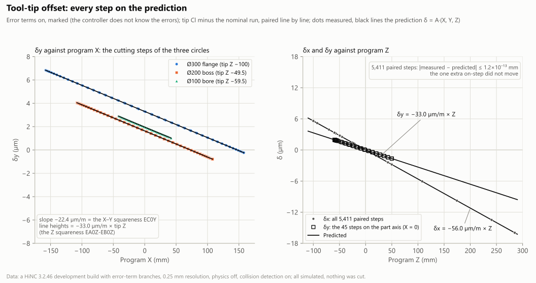
Error terms on, marked: the tool-tip offset of every step (Cl minus the nominal run, program coordinates). Left: on the cutting steps of the three circles, δy against program X is three parallel lines of slope −22.4 µm/m (the X–Y squareness), raised by −33.0 µm/m × the tip height (the Z squareness); right: δx against Z is −56.0 µm/m, δy on the part axis −33.0 µm/m. Dots measured, black lines predicted; all 5,411 paired steps on the prediction within 1.24×10⁻¹³ mm. A HiNC 3.2.46 development build with error-term branches, physics off.
The roundness: the X–Y squareness cuts the circles oval
Each diameter is read at seven sections 5 mm apart (Ø300 at z −90…−60, Ø200 and the bore at z −40…−10; section 04 at z −75 and −25 as in the paper), from the vertices within ±0.5 mm of the section's height and 0.3 mm of the design radius, about 24,000 / 16,000 / 8,000 per section. The signed distance is fitted against the azimuth θ as d = a0 + a1 cos θ + b1 sin θ + a2 cos 2θ + b2 sin 2θ; the simulated RONt is 2√(a2² + b2²), the peak-to-valley once radius change and centre offset are taken out, as a Talyrond centres the part. The fit leaves out the scallops and higher harmonics.
| Ø300 flange | Ø200 boss | Ø100 bore | |
|---|---|---|---|
| Tool-centre radius R_c | 158 mm | 108 mm | 42 mm |
| b2, mean of 7 sections (predicted −s·γR_c/2) | −1.7674 (−1.7696) µm | −1.2107 (−1.2096) µm | +0.4700 (+0.4704) µm |
| b2, spread over the 7 sections | 0.0007 µm | 0.0011 µm | 0.0012 µm |
| Simulated RONt, mean of 7 sections (predicted γR_c) | 3.535 (3.539) µm | 2.421 (2.419) µm | 0.940 (0.941) µm |
| Largest |a2| | 0.0070 µm | 0.0022 µm | 0.0002 µm |
| Vertex residual after the fit, p01–p99 half-width | 0.272 µm | 0.144 µm | 0.122 µm |
| RONt measured on WP1 at position 04 (paper) | 10.36 µm | 9.43 µm | 5.10 µm |
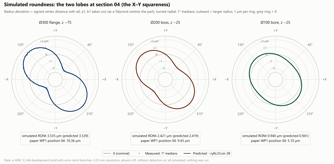
Simulated roundness at section 04: the radius deviation of the wall cut at 0.25 mm once radius change and centre offset are taken out (as a Talyrond centres the part), 1° medians, 1 µm per ring. All three diameters are ellipses with the long axis at 135°/315° (outward = larger radius), sized by the tool-centre radius: simulated RONt 3.535 / 2.421 / 0.940 µm (predicted γ × tool-centre radius 3.539 / 2.419 / 0.941); the paper measured 10.36 / 9.43 / 5.10 µm on WP1 at position 04. A HiNC 3.2.46 development build with error-term branches.
The section centres: the Z squareness tilts the common axis
| Ø300 flange | Ø200 boss | Ø100 bore | |
|---|---|---|---|
| Centre shift against |z| over 7 sections (predicted 65.00 µrad) | 65.10 µrad | 64.94 µrad | 65.02 µrad |
| Largest distance of a section from that line | 0.0009 µm | 0.0004 µm | 0.0005 µm |
| Azimuth of the summed (a1, b1) (predicted 30.51°; bore 210.51°) | 30.46° | 30.59° | 210.53° |
| Section 04, measured (a1, b1) | (4.203, 2.473) µm | (1.399, 0.826) µm | (−1.403, −0.827) µm |
| Section 04, predicted (a1, b1) | (4.200, 2.475) µm | (1.400, 0.825) µm | (−1.400, −0.825) µm |
The bore's signed distance runs opposite to its radius, so its (a1, b1) points to 210.5° while its centre moves toward 30.5° like the others. The lines of the three diameters pass through program zero within 0.005 µm: the three cylinders share one axis tilted by 65 µrad, and neither of the two tilts changes the roundness — the seven sections' RONt differ by at most 0.0024 µm while their centres move 1.95 µm.
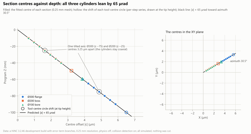
Section centres against depth: the fitted centres of all 21 sections lie on |z| × 65 µrad toward azimuth 30.5° (slopes 65.10 / 64.94 / 65.02 µrad), and so do the shifts of the three tool-centre circles (6.50 / 3.22 / 3.87 µm, at the tip heights). The three cylinders lean together by 65 µrad; the Ø300 and Ø200 centres at section 04 are 3.25 µm apart. A HiNC 3.2.46 development build with error-term branches, 0.25 mm resolution.
The whole wall, its extremes and the 24 boxes
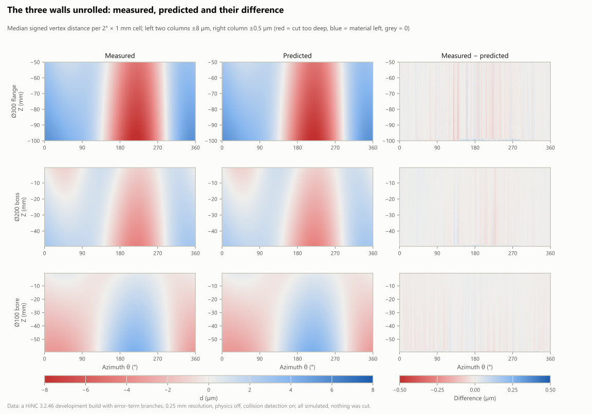
The three walls unrolled (azimuth across, height up), median signed distance per 2° × 1 mm cell: measured, predicted, and their difference. Measured and predicted agree: the outer walls keep material on the +X+Y side (about 30°) and are cut too deep opposite, more so lower down; the bore the other way round. On its ±0.5 µm scale the difference holds only scallop and grid noise. Red = cut too deep, blue = material left, grey = 0, symmetric scales. A HiNC 3.2.46 development build with error-term branches, 0.25 mm resolution.
- Wall vertices minus the prediction, away from the wall ends: p01–p99 −0.175…+0.307 / −0.085…+0.129 / −0.102…+0.109 µm for Ø300 / Ø200 / bore, medians within 0.006 µm.
- The largest deviation sits at the bottom of the flange band (z −99.5…−99.0, 1° medians): −8.18 µm at 222.5° and +5.57 µm at 359.5°, against −8.11 µm at 218.5° and +5.56 µm at 357.5° predicted at the same height; the curve is flat there, so the bin of the minimum moves with the noise.
- The 24 boxes at section 04 hold their predicted means within the plan's tolerance, 24 of 24; the largest difference is 0.132 µm (D300-000, 21 % of its tolerance), the medians within 0.029 µm. The three boxes on uncut faces read 0.
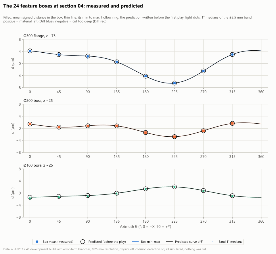
The 24 feature boxes at section 04: mean and min–max of the signed distance in each box against the prediction written before the first play; 24 of 24 within tolerance, means at most 0.13 µm off, medians at most 0.03 µm. Positive = material left (Diff blue), negative = cut too deep (Diff red), symmetric axis. A HiNC 3.2.46 development build with error-term branches, 0.25 mm resolution.
Against the paper
| Ø300 flange | Ø200 boss | Ø100 bore | |
|---|---|---|---|
| Simulated RONt here (γ = 22.4 µm/m) | 3.535 µm | 2.421 µm | 0.940 µm |
| Each diameter's own ballbar γ (22.4 / 10.5 / 13.8 µm/m) × R_c, derived | 3.54 µm | 1.13 µm | 0.58 µm |
| The paper's Fig. 19 squareness, γ × D | 6.72 µm | 2.10 µm | 1.38 µm |
| RONt measured on WP1, mean of 7 positions | 10.13 µm | 9.39 µm | 5.37 µm |
| Share of WP1 explained here | 34.9 % | 25.8 % | 17.5 % |
| Residual squareness after compensation (DBB2 Ø300, −6.2 µm/m) × R_c, derived | 0.98 µm | 0.67 µm | 0.26 µm |
| RONt measured on WP2, mean of 7 positions | 6.16 µm | 5.71 µm¹ | 5.59 µm |
¹ The seven WP2 positions of the paper's Table 12 average 6.00 µm, not the 5.71 µm the table, the text and Table 14 print; the printed value is used here.
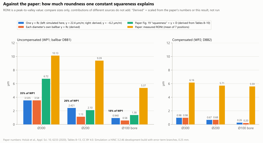
Against the paper. Uncompensated: the simulated RONt (mean of 7 sections) 3.535 / 2.421 / 0.940 µm is 35 % / 26 % / 18 % of the 10.13 / 9.39 / 5.37 µm measured on WP1; with each diameter's own ballbar γ it would be 3.54 / 1.13 / 0.58 µm; the γ × D the paper plots in Fig. 19 is about twice the out-of-roundness one squareness makes. Compensated: the residual squareness scales to 0.98 / 0.67 / 0.26 µm while WP2 still measured 6.16 / 5.71 / 5.59 µm. RONt is a peak-to-valley value: compare sizes only. Paper numbers from Holub et al., Appl. Sci. 10, 6233 (2020), Tables 8–13, CC BY 4.0.
- The paper's conclusion points the right way; the size explains part of it. Of the three squareness errors only the one in the machining plane reaches the roundness, as the paper concludes; a constant X–Y squareness explains a third (Ø300) to a sixth (bore) of WP1's roundness. That the ballbar's squareness changes with the circle's diameter shows that the X–Y error is not all constant either.
- One squareness makes an ellipse whose radii differ by γR_c ≈ γD/2, about half the γ × D the paper plots.
- What the compensation left is mostly not squareness. Scaled, the residual squareness is at most 0.98 µm, while WP2 still measured 5.6–6.2 µm. The causes the paper names — the deflection under the cutting force, and the bore's other machining technology and clearance specification due to system stiffness — are outside a geometric model, as is thermal growth.
- A constant error gives no difference between positions: the paper's WP1 Ø300 ranges 8.81–11.28 µm over its seven positions; here the seven sections differ by 0.0015 µm.
What a controller that knows the errors changes
With the marks cleared and the switch on, the machine still has its errors but the controller's model holds them, as a controller with calibrated kinematics would. On the 1 mm trimmed runs the unmarked and the marked run are bit-identical: the same tool tips and machine coordinates on all 5,412 steps, the same cut, the same Diff counters and the same roundness fits. In a plain three-axis program the controller computes the machine coordinates from the program and its offsets and does not read the chain (what a mark changes), so the errors are cut into the part either way; the one difference is P0 (dilemma 1). On the real machine it is the controller's compensation table — the VCS of the paper — that made WP2 rounder; HiNC does not simulate it.
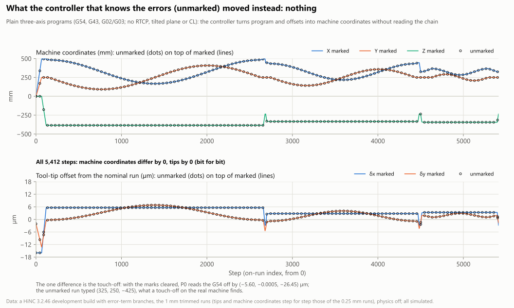
What the controller that knows the errors (marks cleared) moved instead: nothing. Over the 5,412 steps of the 1 mm trimmed runs, the unmarked and the marked run have bit-identical machine coordinates and tool-tip offsets, and the same cut and Diff: in a plain three-axis program the controller does not read the chain, so the error is cut into the part all the same. The one difference: with the marks cleared, P0 reads the G54 off by (−5.60, −0.0005, −26.45) µm, so that run typed what a touch-off on the real machine finds, (325, 250, −425). A HiNC 3.2.46 development build with error-term branches.
The Diff on the part
The pictures below alternate in place between the run with the error terms on (marked) and the control run (off), each put back on the canvas from its recorded stock with its Diff; the camera does not move.
Diff, right view (from +X), alternating in place: error terms on (marked) and off (control). With them on, the walls facing +X turn blue (material left), the flange band more so lower down (about +4.2 µm at section 04); the boss faintly cyan; the uncut lower flange all green; with them off all green. The few saturated specks along the step edges are the 0.5 mm steps flipping a 0.25 mm cell (dilemma 7), not the shape of the error. Diff colour scale ±0.008 mm (red = cut too deep, blue = material left, green = 0, both signs alike); 0.25 mm resolution; a HiNC 3.2.46 development build with error-term branches.
Diff, left view (from −X), alternating in place: error terms on (marked) and off (control). With them on, the walls facing −X turn red (cut too deep), the flange band deepest toward −Y (about 218°), near −8 µm; the boss yellowish green; the uncut lower flange all green; with them off all green. Scale, grid and version as above.
Diff, front view (from −Y), alternating in place: error terms on (marked) and off (control). With them on, from red on the left (−X) to blue on the right (+X), stronger lower down: the deeper the section, the farther its centre toward +X+Y (about 30°); the uncut lower flange all green; with them off all green. Scale, grid and version as above.
Diff, back view (from +Y), alternating in place: error terms on (marked) and off (control). With them on, from blue on the left (+X) to red on the right (−X); the uncut lower flange all green; with them off all green. Scale, grid and version as above.
Diff, isometric view (from above −X, −Y), alternating in place: error terms on (marked) and off (control). With them on, the flange band reddest on the −X−Y side nearest the camera; the top faces are uncut and stay green; with them off all green. Scale, grid and version as above.
Diff, boss close-up, front view (from −Y), alternating in place: error terms on and off. With them on, the top of the boss shows the two lobes, red around 225° and blue around 315° (±1.2 µm), with the lean added lower down; the flange band exceeds ±2 µm and saturates; with them off all green. Diff colour scale ±0.002 mm; 0.25 mm resolution; a HiNC 3.2.46 development build with error-term branches.
Diff, boss close-up, back view (from +Y), alternating in place: error terms on and off. With them on, the top of the boss leans red (yellow-orange) around 45° and blue (cyan) around 135°: the X–Y squareness cuts the circle into an ellipse with its long axis at 135°/315°; the lean is added lower down; with them off all green. Diff colour scale ±0.002 mm; 0.25 mm resolution; a HiNC 3.2.46 development build with error-term branches.
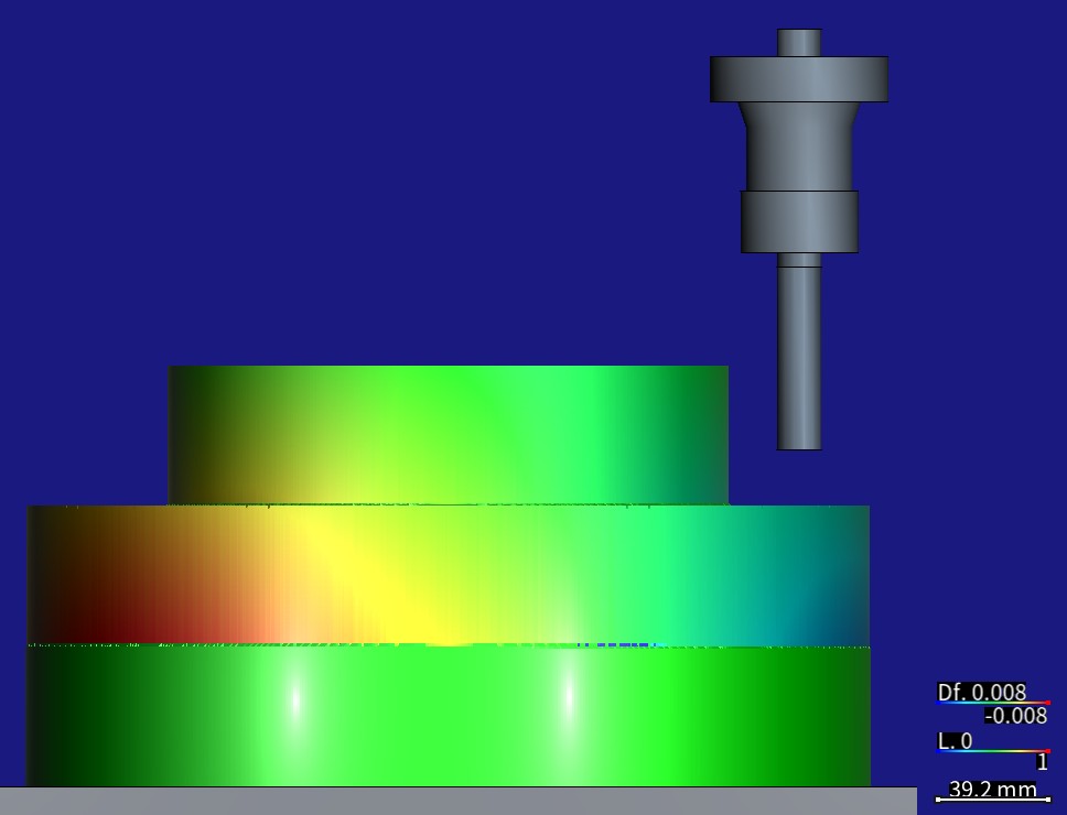
The stock cut with error terms on (marked) put back and the parking program NC/pose-d200.nc played on
it (no cut): the T1 Ø16 four-flute end mill in its ER25/BT40 collet chuck parked in the air beside the
boss (front view, from −Y). The part shows that run's Diff, reddish on the left (−X), bluish on the right
(+X). Diff colour scale ±0.008 mm; 0.25 mm resolution; a HiNC 3.2.46 development build with error-term
branches.
Collision detection was on in all ten runs and reported no collision; at the bottom of each circle the holder's nose stands 10.5 / 20 / 20.5 mm above the local stock (bore / flange / boss).
What it brings
- For a machining engineer. The three squareness errors of one three-axis machine act very differently on a circle-milled part. The squareness of the machining plane's two axes cuts every circle into an ellipse, out of round by γ × the tool-centre radius — 3.5 µm on Ø300 for this machine's 22.4 µm/m. The two Z squareness errors, the largest constant terms the laser tracer found, leave the roundness alone and tilt the axis the cylinders share: 3.25 µm over a 50 mm wall against the end face. To make such a part rounder, compensate the machining plane's squareness; whoever measures only roundness will not see the Z squareness — the squareness or position of the axis against the end face will. In a plain three-axis program, a controller that knows the errors cuts the same part; on a real machine the improvement comes from the compensation table. With HiNC, the constant squareness measured on a machine can be put into the model to see its shape and size on one's own part before it is cut.
- For a teacher or a student. How a squareness travels through the kinematic chain into the tool-tip offset δ = A·(X, Y, Z); why the out-of-roundness is set by the tool-centre radius (the ellipse is the tool-centre path, the wall its envelope), which is also why the paper's γ × D is about twice the out-of-roundness; why a Talyrond centred on the part does not see a tilted axis; and how a real touch-off and HiNC's P0 differ (dilemma 1).
- For someone weighing the approach. A base built from a paper's numbers alone, an error-term copy, and ten plays totalling 240.3 s at most 6.51 GiB each; predictions written before the first play and met to 1.24×10⁻¹³ mm on the tool tip, 0.0022 µm on the lobe term and 0.16 % on the axis tilt; the method's own limits — artefacts of the distance search, steps flipping in the mesh, lines of vertices reading off, a control 5 % inside its threshold — written down with the results.
| Run | Programs | Grid | Steps | Wall clock | Peak memory |
|---|---|---|---|---|---|
| Trimmed, nominal / on / control / unmarked | three | 1 mm | 5,411 / 5,412 / 5,411 / 5,412 | 10 s each | 0.69–1.00 GiB |
| Probe, nominal / on / control | the boss | 0.25 mm | 1,889 each | 15–20 s | 1.57–2.85 GiB |
| Whole part, nominal | three | 0.25 mm | 5,411 | 40.0 s | 3.52 GiB |
| Whole part, control | three | 0.25 mm | 5,411 | 50.1 s | 6.51 GiB |
| Whole part, on | three | 0.25 mm | 5,412 | 55.2 s | 6.43 GiB |
Each run played on a freshly restarted private instance on a shared 32-thread server, so its peak memory is its own, Diff and export included; the wall clock is polled every 5 s.
Honest limits
- An error term holds a constant. The paper's machine has more: position-dependent positioning, scale, straightness and angular errors, a volumetric error map, the ballbar's reversal spikes and servo mismatch, thermal growth; none is represented, and neither is the VCS compensation itself (see Machine Geometric Error).
- The scale error is left out. The ballbar's scaling mismatch (12.3 µm on Ø300 before compensation) adds two lobes along 0° and 90°; a scale can only be written into the axis vector of the axis branch itself, which is not an error term.
- One γ for three diameters. The ballbar's squareness changes with the circle; with each diameter's own value the boss and the bore would be 1.13 and 0.58 µm out of round (derived, not run).
- The signs are only partly sourced. The laser tracer's errors follow ISO 230-1 as the paper states; the ballbar's squareness has no stated sign and takes the sign of the laser tracer's E_C0Y. The signs set the direction of the ellipse's long axis and of the tilt, not their size; the paper does not relate the Talyrond's 0° to the machine axes, so the direction cannot be compared with the paper's polar plots.
- The Z values are read off a chart (±1–2 µrad; the RPTU part 8 case read the same bars as 33.2 and 55.9 µrad and the X–Y bar as 24.4 µrad, typed in to 0.0001° as 33.16, 55.85 and 24.43 µrad), and the lean of the walls rests on the spindle tilting with Z, which the paper did not measure. The roundness and the shift of each circle do not depend on it.
- “After compensation” is a linear scaling, not a run.
- Geometry only. Physics is off: the deflection the paper names, heat and chatter are outside this case; Al6061-T6 standing in for EN AW-2007 does not change the result.
- The process is the agent's. 0.5 mm left instead of the paper's 0.02 mm, one climb pass per face, Table 2's feed rather than Section 2.4.1's; the bore milled like the others, though the paper used another technology for it. The machine is a shapeless three-axis machine with the paper's travels, not a model of the paper's machine.
- The roundness evaluation is not the paper's, whose filter and reference circle are not stated: the fit to the second harmonic measures only the share the error terms cause.
- One step per revolution does not sweep, so the walls carry scallops; they cancel between the runs compared (dilemma 3).
- The mesh-distance search misreads next to large triangles; every flagged value was checked by brute force (dilemma 7). The lines of vertices reading off are unexplained (dilemma 8).
- The work offset of the error-term runs is typed, as a touch-off would find it; HiNC's P0 measures differently (dilemma 1).
What a reader can take to their own case
- Put the pivot of an error at the touch-off pose, then the work offset a touch-off finds does not move, and nothing has to be typed differently between the runs.
- Use the tool-centre radius for out-of-roundness: γ × R_c, not γ × D.
- Expect a tilted axis, not a lost roundness, from a Z squareness; check it with the axis against the end face, and remember the modelled spindle tilts with Z.
- In a plain three-axis program, marking does not matter for the cut; only RTCP, a tilted plane or CL playback let the controller compensate (see what a mark changes).
- Compare runs by program line, not by step number, when one run has a step the other has not.
- Fit low harmonics on sections; at 0.25 mm a fit reads lobes of a few tenths of a micrometre through scallops several micrometres high.
- Check extreme mesh distances by brute force before reading them as shape, and keep judged regions away from features only two cells wide.
- Write the fallback's trigger as a number, on a quantity the run can fail.
Source and licence
- Article: M. Holub, R. Jankovych, J. Vetiska, J. Sramek, P. Blecha, J. Smolik, P. Heinrich,
“Experimental Study of the Volumetric Error Effect on the Resulting Working Accuracy—Roundness”,
Applied Sciences 10(18), 6233 (2020), MDPI, published 8 September 2020,
https://doi.org/10.3390/app10186233. Search terms if the link moves:
Experimental Study of the Volumetric Error Effect on the Resulting Working Accuracy Roundness,app10186233. - Licence: Creative Commons Attribution 4.0 International (CC BY 4.0), as the last page of the article states: “© 2020 by the authors. Licensee MDPI, Basel, Switzerland. This article is an open access article distributed under the terms and conditions of the Creative Commons Attribution (CC BY) license (http://creativecommons.org/licenses/by/4.0/).”
- Attribution: “Measured data and part dimensions: M. Holub, R. Jankovych, J. Vetiska, J. Sramek, P. Blecha, J. Smolik, P. Heinrich, ‘Experimental Study of the Volumetric Error Effect on the Resulting Working Accuracy—Roundness’, Applied Sciences 10(18), 6233 (2020), https://doi.org/10.3390/app10186233. © 2020 by the authors, licensee MDPI, Basel, Switzerland. Licensed CC BY 4.0 (https://creativecommons.org/licenses/by/4.0/), provided as-is without warranties (CC BY 4.0 Section 5). Changes: the stock and design models, the NC programs and the HiNC project are ours, built from the article's numbers.”
- What was used and changed: the article's printed numbers only — the travels of Table 1, the cutting data of Table 2, the part of Fig. 3a and the positions of Fig. 11, the ballbar squareness of Tables 8–10, the laser tracer bars of Fig. 6 (read off the chart), the volumetric error of Fig. 7, the RONt of Tables 11–13, the squareness of Fig. 19 (read off the chart; it equals Tables 8–10 × D) and the conclusion of Section 5. No figure of the article is reproduced. The stock and design models, the NC programs, the machine set-up and the HiNC project are the agent's, built from those numbers; where the errors sit, their pivots and the touch-off are the agent's choices. The pictures are HiNC simulations, and the charts are drawn from HiNC's per-step results, the cut part's mesh and the numbers of the paper's tables. Everything on this page is simulated; no part was cut.
See Also
- Building Virtual Machine Tools: Error terms — where an error term may go, what a mark changes, the switch and work offsets
- Kinematic Topology: Error-Term Branches — the model: the controller on the nominal chain, the machine with the errors
- Machining Issues Outside the Model: Machine Geometric Error — the geometric errors that cannot be represented, and this paper's numbers
- RPTU Benchmark Part 8 on a Machine with Three Measured Squareness Errors — the same paper's three laser-tracer squareness errors on an ISO 10791-7-style test piece
- Geometry Validation — the geometry difference, its detection radius and its colour scale
- Program Zero Alignment — P0, and typing in a measured work offset
- Project Construction — the build order the base project follows
- Showcase — the other cases and how a case page reads