The Cubic Machining Test of JMMP 2021 with the Eight Rotary-Axis Errors a Ball Bar Measured: Zones II and III Stand 0.43 / 0.23 µm above Zone I, and a 10 µm Tool-Length Error Shifts Them by 1.34 µm
In 2021 Li, Ogata, Sato, Shirase and Sakamoto (J. Manuf. Mater. Process. 5, 51) ran the “cubic machining test” on a vertical five-axis machine (a DMG Mori NMV 1500 DCG) whose C rotary table rides on a B tilting table. One 48 × 48 mm face is split into 3 × 3 zones: in the central zone I the tool axis stands vertical, in the four edge zones II it tilts 30° toward the centre, in the four corner zones III it tilts 30° and is turned by 45°. An R3 ball-end mill cuts all nine under TCP, and the test reads how far each zone stands above or below zone I inside the central 40 × 40 mm. A ball bar identified eight location and orientation errors of the two rotary axes (their Table 5), from which the authors simulated −1.4 to +0.9 µm (Fig. 11a); they measured +4.4 to +6.1 µm (Fig. 7a), and put the difference down to the ball's edge form, about 4 µm off between 0° and 30° (Fig. 13). They also made the controller hold the tool 10 µm too long and too short: their formula and simulation both move the tilted zones by ∓1.3 µm against zone I (Eq. 2, Table 6).
The article comes with no data set, no NC and no model, so an AI agent built the part, the program, the machine set-up and the HiNC project anew from its description; this page is the case's first public page. It then puts the eight Table 5 errors into the batch's generic B/C table-table machine as two error terms:
BY-Table5: the position and orientation errors of the B axis' average line (δx_BY, δy_BY, δz_BY and α_BY, β_BY, γ_BY), one General Transform (a rotation and a translation in one branch), directly upstream of the B axis.CB-Table5: the errors of the C axis against the B axis (α_CB, δx_CB), one General Transform, directly upstream of the C axis.
One Fanuc G43.4 (TCP) program cuts the nine zones, and it was played six times at 0.25 mm on a HiNC 3.2.46
development build with error-term branches:
- Nominal: error terms off. Its cut is the ideal geometry of every geometry difference (Diff) that follows.
- Control: error terms off again, with a Diff, for the noise floor.
- On: error terms on, the errors marked: the controller does not know them.
- Unmarked: error terms on, the marks cleared: the controller knows the errors, as a controller with calibrated kinematics would.
- eLp, eLm: error terms off, the controller's tool length 10 µm too long and too short.
What came out:
- The tool tip. On all 74,661 steps of the on run's TCP section the tip's offset lies on the prediction written before the first play, d = W⁻¹W₀(P + g) − P, within 7.4 × 10⁻¹² mm (P is the tip the program asks for, g the touch-off work offset typed in, W and W₀ the table side's transform from the part to the machine with and without the errors). On the cut face the tip moves sideways by up to 35.0 µm and up or down by at most 1.52 µm.
- The zone heights. The face the two runs' ball centres sweep, the continuous envelope, differs inside each measurement box by −0.0002 µm in zone I, +0.4326 to +0.4329 µm in the four zones II and +0.2337 to +0.2340 µm in the four zones III, within 0.0040 µm of the plan's prediction: +0.433 and +0.234 µm against zone I, the four zones of a kind within 0.0003 µm of each other. Most of it is δx_BY (+1.000 µm), β_BY (−0.464 / −0.657 µm) and δz_BY (−0.087 µm); the other five errors move a zone by 0.001 µm or less with the part placed as here.
- Every face also tilts. From a box's centre to its farthest corners the face rises and falls by ±0.68 (zone I), ±0.98–0.99 (zones II) and ±0.89 µm (zones III). γ_BY and α_CB, which tilt zones II and III most, move the zone means by 0.0007 µm or less: a test that reads zone means cannot see the tilt.
- The tool length. With the controller's tool length 10 µm too long, zone I stands +10.0000 µm and the tilted zones +8.6600 to +8.6603 µm higher, −1.3397 to −1.3400 µm against zone I; 10 µm too short turns every sign (+1.3395 to +1.3397 µm against zone I). That is (1 − cos 30°)·eL = 1.3397 µm within 0.00024 µm; the article's Table 6 gives −1.3 and +1.3 to +1.4 µm.
- The controller that knows the errors puts the tip back on the program, all but a constant 5.85 nm, a
second-order term the typed work offset brings in. The tilted faces still stand +0.0500 µm high: under
G43.4the program commands B and C as numbers, so a calibrated controller puts the tip back on the program point while the tool's direction on the part keeps the errors' rotation, and the ball's lowest point moves by r(a′z − az) = 0.0497 µm (r = 3 mm, the ball's radius; az and a′z the z components of the programmed and the actual tool direction). The plan had predicted only that the tip equals the nominal one. - Six of the plan's twelve criteria failed as written, each for a cause measured afterwards:
- The motion resolution makes one step per spindle revolution, every 10 ms at 6000 rpm, and a 16 mm row at 2000 mm/min lasts exactly 48 spindle periods, so a row takes 48 steps or 49: the runs' step counts differ (criterion 4), and the steps could only be paired by their place along the row (criterion 6).
- 143 steps outside the TCP section follow other rules (criteria 5 and 6).
- Each step places one ball, with no sweep between steps, and the ridges between two steps stand 4.63 µm high. The Diff's box means the plan judged on (criteria 8–10) read those ridges, up to 0.84 µm off the face height.
- The unmarked run's 5.85 nm fails the unmarked half of criterion 6. None of them is an error of the error terms or of the predictions: the plan did not foresee how HiNC makes its steps and wrote its per-step formulas for the TCP section only; the fourth is a prediction for the unmarked run that missed.
- Against the article: here +0.234 to +0.433 µm, the four zones of a kind alike; the article's simulation −1.4 to +0.9 µm, every zone different. The difference is where the part sits relative to the B and C axes, which the article does not give: here the part is centred on the C axis with its face at the height where the two axis lines meet, which leaves five of the eight errors without a lever. The measured +4.4 to +6.1 µm holds the edge form error, which the model's perfect ball does not have.
- The cost: ten runs (four trimmed at 1 mm, six of the whole part at 0.25 mm), about 90 s each on a shared 32-thread server, at a peak memory of at most 1.506 GiB.
Everything here is simulated; nothing was cut.
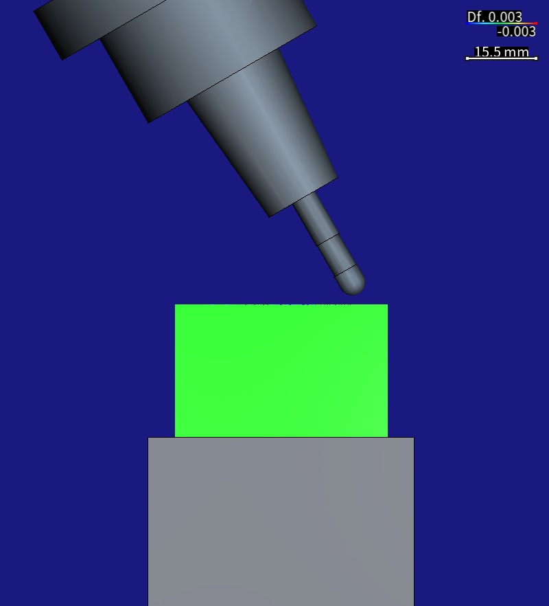
The cut of the run with the error terms on (marked), put back on the canvas, and the parking program
NC/pose-t1.nc played on it (no cutting): the R3 ball-end mill DLC2MBR0300 in its slim shrink-fit holder
(a nose of D18 widening to D24 over 32 mm on an SK40 body; the holder and the stick-out are chosen, the
article gives none), tilted 30° at B30 C180, its lowest point 2 mm above the centre of zone II +X (front
view, from −Y). Ball, neck, shank and shrink-fit holder are in view, the top of the SK40 body cut off by
the frame; no collision. The run's Diff lies on the part, colour range ±0.003 mm: red = cut too deep,
blue = material left, green = 0, both signs weighted alike. The sides were not cut and are green; at this
angle the top face shows only a row of fine dots along its edge (the zones' stripes and speckles are in the
Diff pictures below). A HiNC 3.2.46 development build with error-term branches, 0.25 mm.
| The cubic test at 0.25 mm on a HiNC 3.2.46 development build with error-term branches | Predicted before the first play | Measured |
|---|---|---|
| Tip minus the nominal tip minus d, the 74,661 TCP steps of the on run | 0 (the plan allowed 1 × 10⁻⁹ mm) | at most 7.4 × 10⁻¹² mm |
| Machine X, Y, Z minus the nominal, minus R_B R_C g (on run, TCP section) | 0 | at most 6.4 × 10⁻¹² mm; B and C within 5.7 × 10⁻¹⁴° |
| Face height change of the ball paths in the measurement boxes: zone I / zones II / zones III | −0.00001 / +0.4291 to +0.4324 / +0.2297 to +0.2335 µm | −0.0002 / +0.4326 to +0.4329 / +0.2337 to +0.2340 µm |
| The same relative to zone I, zones II / zones III | +0.43 / +0.23 µm, each within 0.03 µm | +0.4329 to +0.4331 / +0.2339 to +0.2342 µm |
| Controller's tool length +10 / −10 µm: tilted zones relative to zone I | ∓1.3397 µm | −1.3397 to −1.3400 / +1.3395 to +1.3397 µm |
| Unmarked: the tip | the nominal tip | P + (4.010, 4.246, 0.323) nm at every TCP step, 5.85 nm |
| Unmarked: the tilted faces | the tip unchanged (so no face height change) | +0.0500 µm, the turned tool axis (r(a′z − az) + e_z = 0.0501 µm) |
| Diff box means of the on run against the face height change | the plan judged the box means | up to 0.84 µm off: the ridges between steps |
| Control against nominal | 0 | every step bit for bit; every vertex within 5.0 × 10⁻¹⁰ mm |
| Server time and peak memory of a whole-part run | — | about 90 s, at most 1.506 GiB |
The case
When the case was collected, the source was the article alone: it has no data set ("The data presented in this study are not available."), no NC and no model, and every number is printed in the PDF. HiNC's product owner added it on 2026-10-07 as the eighteenth error-term case, on the recommendation of a search for articles to build error-term cases on: of the candidates it is the only one cut under TCP, so a controller that does not know the errors (marked) and one that does (unmarked) can both be shown, and its tool-length error comes with a closed-form check.
The case asks three questions:
- How much do Table 5's eight errors raise or lower each zone?
- With the controller's tool length 10 µm off, do the tilted zones move against zone I by exactly (1 − cos 30°)·eL?
- Does a controller with calibrated kinematics (unmarked) cut the nominal part again?
What the agent was given:
- The article (CC BY 4.0) and the numbers it prints:
- The machine (Section 2, Fig. 1): a vertical five-axis DMG Mori NMV 1500 DCG, a C rotary table on a B tilting table, X, Y and Z on the spindle side. Where the B and C axis lines, the table and the part sit is not given (it is in another article of the authors, not open access), nor is the controller.
- The errors (Section 4.3, Tables 4 and 5, Fig. 9, Eqs. 4–11): the ball bar identified δx_BY 2.0, δy_BY −11.0 and δz_BY −0.647 µm, α_BY 0.0017°, β_BY 0.0019° and γ_BY 0.0210°, α_CB −0.0054° and δx_CB 9.7 µm.
- The test part (Section 2, Fig. 2, Table 1): one 48 × 48 mm face split into 3 × 3 zones, each cut in a zigzag with rows 0.1 mm apart; AA7075; the ball-end mill DLC2MBR0300 (D6, two flutes, 30° helix, DLC coated); a finishing depth of 0.1 mm at 2000 mm/min and 6000 rpm, then a zero-depth pass. The block's other dimensions, the clamping, the order of the zones and the moves between them are not given.
- The measurement (Section 2, Fig. 7, Table 3): a contact profilometer over the central 40 × 40 mm, paths 2 mm apart, each zone's mean height minus zone I's.
- The tool length (Sections 3 and 4.2, Eqs. 1 and 2): under TCP a tool-length error eL of the controller changes zone I's depth by eL and a zone tilted 30° by eL cos 30°, so a tilted zone and zone I differ by (1 − cos 30°)·eL.
- The simulation (Section 4.3, Fig. 11, Table 6) and the edge form (Section 5, Fig. 13).
- The base project, which the agent built for this case from the article:
- The machine: the batch's generic B/C table-table machine (copied from the NIST cone frustum case): B turns about −Y and C about −Z, and their axis lines meet 100 mm above the table; X ±400, Y ±300, Z −250 to 650 mm, B ±110°; homing and tool changes at Z 600; a Fanuc controller. All of it is chosen: the article gives neither the machine's geometry nor its controller.
- The part: a 48 × 48 × 30 mm AA7075 block with 0.1 mm left on top, on a 60 × 60 × 70 mm riser. The cut top face therefore lies exactly at the height where the B and C axis lines meet, centred on the C axis: program zero is the B/C pivot, and G54 is (0, 0, 0).
- The program
NC/cubic-tcp.nc(2,940 lines): each zone a zigzag of 161 rows along X, each row 16 mm, 0.1 mm apart, at 2000 mm/min and 6000 rpm, underG43.4 H01. The program's points are the tool tip: the ball centre stands z = r above the zone, and tip = ball centre − r·a with a = (sin B cos C, sin B sin C, cos B). Zones II at B30 with C 180, −90, 0 and 90 (+X, +Y, −X, −Y), zones III at C −135, −45, 45 and 135, the tool's upper end leaning toward the centre as in the article's Fig. 2. The zones run I, II +X, +Y, −X, −Y, then III +X+Y, −X+Y, −X−Y, +X−Y, moving between them with the tip at z 30; the zero-depth pass is left out (all chosen).NC/pose-t1.nconly parks the tool above zone II +X for the holder pictures and is switched off in the mission otherwise. - The tool: T1, the R3 ball-end mill DLC2MBR0300 (read: D6, two flutes, 30° helix; chosen: flute length 6, a D5.7 neck to 14 mm, a D6 shank, 60 mm overall, 25 mm stick-out, a tool length of 95 mm), in a shrink-fit holder (chosen: a nose of D18 widening to D24 over 32 mm, an SK40 body; the article names no holder).
- Its acceptance: saved and reloaded with no message; after a reset P0 reads (0, 0, 0); a 1 mm rough
run of 74,690 steps in 90 s,
Finished, with one message only,Sys-Init--FileLines(2,940 lines), and no collision; a cycle time of 12 min 15 s.
- HiNC's error terms. An axis or the spindle of the machine chain can be given an error term, a static
branch of its own just before the axis's branch: it carries an error measured on the real machine rather
than part of its design. The controller,
XyzabcSolver, which turns NC into machine coordinates, RTCP included, always solves on the nominal chain, taking the marked branches as absent. While the project's Enable Error Terms switch is on, the simulated machine keeps the marked branches as it moves, cuts and checks collisions. So the error is cut into the part, as on a real machine whose controller does not know it. Under RTCP (G43.4) an unmarked error is part of the machine the controller knows, and the machine coordinates follow it: a controller with calibrated kinematics (Error-Term Branches). - Touch-off and P0. HiNC's P0 measures program zero on the nominal chain. On a real machine the work offset found by touching off already holds the constant shift the errors cause at the touch-off pose; to reproduce a given shop's result, the manual says to type in the work offset that shop measured (work offsets on a machine with error terms).
- A placement rule. HiNC's product owner ruled on 2026-10-06 that an error term goes only directly
upstream of a role branch, an axis X … C or the spindle, on a new anchor of its own named after that
branch with
errafter it. - The request. HiNC's product owner asked for error-term showcases built on earlier cases, product cases and paper cases alike, with the heavy runs on a shared server, and on 2026-10-07 added the two articles the search recommended as the seventeenth and eighteenth cases.
What nothing states:
- Where the part sits relative to the B and C axes: the article does not say. Here the part is centred on the C axis with its face at the height where the two axis lines meet (dilemma 1).
- About which point the angular errors turn: how far an angular error moves a point depends on the point it turns about, and the article gives no reference point. Here the errors turn about the point where the nominal B and C lines meet (dilemma 1).
- Which way the signs go: the plan takes each Table 5 value as a rotation or translation of the stretch downstream; the article's Eq. 4, read literally, goes the other way (dilemma 2).
- What a touch-off would find: the manual only says to type in what the shop's touch-off measured. Where the pivots sit, and whether a General Transform turns or translates first, decides what a touch-off finds; the agent derived it from the machine chain (dilemma 3).
- Where the tool-length error goes: it is not an error of the machine but the tool length the controller holds, so it is not an error term but an axial wear typed into the tool offset (next section).
- How many steps a row takes, and what the cut face looks like: a row lasts exactly 48 spindle periods, so its step count flips between 48 and 49 (dilemma 4), and each step places one ball, leaving a ridge between steps (dilemma 6).
What is new here:
- The base was built for this case from the article, not taken from an accepted case: the agent wrote the stock, the nine zones' program and the parking program, marking every value read, derived or chosen, built the base project through HiNC's REST interface and accepted it at 1 mm.
- One error term holds a rotation and a translation: each is a General Transform.
- Two error terms upstream of the two rotary axes, under a TCP program: whether the controller knows the errors changes the part.
- An error on the tool side: one run each with the controller's tool length 10 µm too long and too short (error terms off), against the article's Eq. 2 and Table 6.
- The part reads the zone means of a face a ball-end mill cuts, as the article's test does.
What the agent built
Each value is marked read (from the article or the base case), derived (computed from what was read) or chosen (the agent's decision).
BY-Table5: the B axis line's position and direction errors |
CB-Table5: the C axis' errors against the B axis |
|
|---|---|---|
| Meaning (the article's Table 4) | δx_BY, δy_BY, δz_BY: the B axis' average line off along X, Y and Z; α_BY, β_BY, γ_BY: the angles between the B axis and the Y axis about X, Y and Z | α_CB: the angle between the C axis and the B axis about X; δx_CB: the C axis off the B axis along X |
| Value | translation (2.0, −11.0, −0.647) µm; the three angles (0.0017°, 0.0019°, 0.0210°) taken as one rotation vector, a single rotation of 0.021154° about (0.0804, 0.0898, 0.9927) | −0.0054° about X; translation (9.7, 0, 0) µm |
| Source | read: Table 5; derived: the rotation vector's length and direction | read: Table 5 |
| Where | directly upstream of the B axis branch: a new anchor Berr splits the old frame → B, frame→Berr is named BY-Table5 and carries the General Transform as the B axis's error term, marked; the B axis' Dynamic Rotation (about (0, −1, 0)) moved onto Berr→B with its values unchanged, and Axis B is bound to the new branch |
directly upstream of the C axis branch: a new anchor Cerr, B→Cerr named CB-Table5, a marked General Transform; the C axis' Dynamic Rotation (about (0, 0, −1)) moved onto Cerr→C unchanged, Axis C bound to it |
| Pivot | (0, 0, 0): where the nominal B and C lines meet, which is program zero (chosen) | the same (chosen) |
| What moves with it | the B axis, the C axis, the table, the riser and the part downstream | the C axis, the table, the riser and the part downstream |
| How it acts | HiNC's General Transform turns, then translates: x → Rot·x + t (checked by P0 before the first play, dilemma 3) | the same |
The machine chain, read back after the build: on the table side O→base→frame→Berr→B→Cerr→C→w, on the
spindle side base→X→Y→Z→S→t. C→w mounts the table 100 mm below the pivot; the 70 mm riser and the
30 mm block put the top face exactly at the pivot's height.
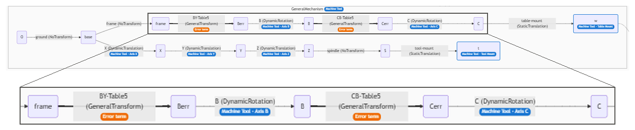
The machine-tool cluster (GeneralMechanism) in the Topology column of the Equipment page. BY-Table5 (frame → Berr, directly upstream of the B axis) and CB-Table5 (B → Cerr, directly upstream of the C axis) are both General Transforms, drawn thick with the orange “Error term” badge; the B and C axes' Dynamic Rotations moved unchanged onto Berr → B and Cerr → C, and the Axis B and Axis C roles are bound to these new branches. Below, the frame → C stretch of the same capture, magnified. A HiNC 3.2.46 development build with error-term branches, English interface.
Touch-off and work offset.
- With the marks on, P0 reads (0, 0, 0) with the switch on or off: P0 measures on the nominal chain.
- A real machine touched off at B = C = 0 finds where program zero really is. The two errors move it to t_B + Rot_B·t_C = (11.700, −10.996, −0.647) µm, written g (|g| = 16.07 µm). With the marks cleared, P0 reads exactly this value, within 2.9 × 10⁻¹⁵ mm.
- The on and unmarked runs type in this g, as the manual's work offsets on a machine with error terms advises for reproducing a shop's cut, rather than pressing P0. The nominal, control, eLp and eLm runs keep (0, 0, 0).
- The typed g is a point on the table, which the controller turns with the nominal B and C.
The tool-length error is not an error term but the tool length the controller holds, the ideal length minus the axial wear: eLp types a wear of −0.010 mm (the controller takes the tool for 10 µm longer), eLm +0.010 mm (10 µm shorter), both with the error terms off.
What was predicted before the first play (the plan and its predictions, from the agent's prediction script):
- Each step's tip, in program coordinates: the controller solves the nominal chain and puts the tip at x = R_B R_C (P + g) in machine coordinates, where P is the nominal tip and R_B, R_C the two axes' rotations. The point the tool really reaches on the part is P′ = W⁻¹x, with W = E_B R_B E_C R_C (E the two errors). The offset d = P′ − P = W⁻¹W₀(P + g) − P, W₀ = R_B R_C, set at every step by its B, C and the nominal tip P. The unmarked and control runs' tips equal the nominal ones.
- The machine coordinates: the on run differs from the nominal by R_B R_C g (the typed G54 turned with the nominal B and C), B and C the same. The plan said the same for the unmarked run, which missed (dilemma 8).
- Each zone's face height: a ball-end mill cutting a plane leaves the face at the ball centre's height
minus r, so dh = d_z + r(a′z − az), where a′ is the tool's actual direction on the part.
- Zone I 0; the four zones II +0.446 to +0.449 µm, the four zones III +0.253 to +0.257 µm (at the centroid of each zone's part inside the article's 40 × 40 mm window).
- In the measurement boxes (each zone shrunk by 1 mm from its neighbours): +0.4291 to +0.4324 and +0.2297 to +0.2335 µm.
- The four zones of a kind nearly alike: each zone is cut at the same place relative to the B axis, only turned by another C.
- Which error does it: δx_BY 1.0, β_BY 0.46 / 0.66 and δz_BY 0.09 µm; α_BY, γ_BY, δy_BY, α_CB and δx_CB 0.001 µm or less each with the part placed as here.
- The tool length: with eL too much in the controller, the tip moves eL·a toward the spindle and the face rises by eL·az: +eL in zone I, +eL cos 30° in the tilted zones, so −(1 − cos 30°)·eL = ∓1.3397 µm against zone I for eL = ±10 µm, the same in every tilted zone.
How the agent managed the work
- Criteria and predictions first. The plan, its predictions and twelve numbered criteria were committed before the first play and not changed afterwards.
- The error-term project. The base project was saved as a new project with its
NC/folder and machine, the two error terms were inserted and read back, and the touch-off was checked with P0 before any play. - Trimmed first, then the whole part, one run at a time. The trimmed set plays the same program four
times at 1 mm (nominal, on, control, unmarked) to check the build, the per-step formula and the unmarked
run; the whole part plays six times at 0.25 mm, and every number on this page comes from those six. The
trimmed and whole-part runs have the same per-step series (tip, machine coordinates, program lines) step
by step; only
IsTouchedchanges with the grid. - A fresh instance for every run, restarted before it, so each run's peak memory is its own.
- The nominal cut as the ideal geometry. The nominal run exported its cut, and every other run's Diff compares with it, so the Diff holds only what differs between two runs, not the scallops the toolpath itself leaves.
- The message level. For the evidence script, which reads the lines each program ran,
IsTouchedand every message from the Message level up, the on run was played a second time; its record is that second play, and its per-step series and cut equal the first play's bit for bit. The other runs are vouched for by their messages from the Warning level up and by the same sequence of program lines (FileNo, LineNo) step by step, as the plan allows. - Verdicts and numbers from the records. A check script judged criteria 3–12 from the records on the shared server, and the agent's analysis script recomputed every number on this page from the records, keeping each with its source; the two agree within 5 × 10⁻⁷ µm.
- Pictures in both interface languages.
- Where a person stepped in. HiNC's product owner asked for error-term showcases built on earlier cases, product cases and paper cases alike, with the heavy runs on a shared server, ruled where an error term may go, and added this article on 2026-10-07. The base project, the placement of the part, the pivot, the sign convention, the touch-off value, the predictions and the criteria are the agent's.
The runs:
| Run | Grid | Enable Error Terms | Marks | G54 | Controller's tool length | Purpose |
|---|---|---|---|---|---|---|
| t-nominal | 1 mm | off | marked (not in effect) | 0 | as built | trimmed: nominal, exports its cut |
| t-on | 1 mm | on | marked | g | as built | trimmed: the controller does not know the errors |
| t-control | 1 mm | off | marked (not in effect) | 0 | as built | trimmed: control |
| t-unmarked | 1 mm | on | cleared | g | as built | trimmed: the controller knows the errors |
| f-nominal | 0.25 mm | off | marked (not in effect) | 0 | as built | whole part: nominal, exports the ideal geometry |
| f-control | 0.25 mm | off | marked (not in effect) | 0 | as built | whole part: control, the noise floor |
| f-on | 0.25 mm | on | marked | g | as built | whole part: the controller does not know the errors |
| f-unmarked | 0.25 mm | on | cleared | g | as built | whole part: the controller knows the errors |
| f-eLp | 0.25 mm | off | marked (not in effect) | 0 | 10 µm long (wear −0.010 mm) | whole part: the controller's tool length too long |
| f-eLm | 0.25 mm | off | marked (not in effect) | 0 | 10 µm short (wear +0.010 mm) | whole part: the controller's tool length too short |
Common to every run:
- Physics off: this case is about geometry only. Collision detection on, pause on failure off.
- Motion resolution Feed Per Cycle: one step per spindle revolution, every 10 ms at 6000 rpm, 1/3 mm apart at 2000 mm/min (dilemmas 4 and 6; Machining Motion Resolution).
- The Diff (Geometry Validation): detection radius 1 mm, colour range ±0.003 mm; ±0.012 mm for the eLp and eLm pictures.
- The parking program
NC/pose-t1.ncis off, and played only for the holder pictures. - Every run exports its cut; each run with a Diff also records its final stock, which the pictures put back on the canvas.
The dilemmas
Each one is told as its situation, the risk had it been missed, how it was noticed, the resolution, and the evidence that the resolution held.
1. The article gives neither the part's place against the B and C axes nor the angular errors' reference point
- Situation. Where the B and C axis lines, the table and the part of the article's machine sit is in another article of the authors, not open access, and Table 5 does not say about which point its angles turn. How far an angular error moves the part depends on the point it turns about and on how far the part lies from it.
- Risk. Another placement changes both the size and the pattern of the zone heights. Saying from this case what the article's machine “should” show would claim too much.
- How noticed. Reading the article.
- Resolution. A placement that can be stated plainly, written into the plan: the part centred on the C axis with its face at the height where the B and C lines meet, and both errors turning about that point, which is program zero. Its cost is written down too: placed so, α_BY, γ_BY, δy_BY, α_CB and δx_CB only shift the part sideways or have no lever, 0.001 µm or less each on a zone mean; the result is symmetric, cannot reproduce the asymmetry of the article's Fig. 11a, and can be set against the article only qualitatively.
- Evidence. The one-error-at-a-time contributions of the prediction (in the zone-height results below); the four zones of a kind within 0.0003 µm of each other.
2. Which way Table 5's signs go
- Situation. The plan takes each Table 5 value as a rotation or translation of the stretch downstream, from the part toward the machine: x → Rot·x + t. The article's Eq. 4 multiplies the tip in machine coordinates by M_B, M_γBY … M_δxBY to reach the part's coordinates, and Eqs. 6–11 write +δ and +angle; read literally, every error then acts the other way.
- Risk. Read literally, the zone heights against zone I turn over. Writing “the same sign as the article” or “the opposite sign” would have no ground either way.
- How noticed. The analysis reread Eqs. 4–11 and recomputed the same chain with all eight values reversed.
- Resolution. The convention was set by the plan before the first play and stays; this page gives both readings. The comparison with Fig. 11a is qualitative anyway, as the part's place is unknown (dilemma 1).
- Evidence. The plan's reading: zones II +0.4457 to +0.4490 µm, zones III +0.2532 to +0.2569 µm (centroids, against zone I); all eight reversed: zones II −0.4524 to −0.4491 µm, zones III −0.2603 to −0.2566 µm.
3. A General Transform turns, then translates: the first touch-off value was 4 nm off
- Situation. When the batch's tools gained the General Transform for this case, they assumed it translates first and then turns, and the first touch-off work offset was computed that way: (11.704, −10.996, −0.648) µm. The error-term project was built with it.
- Risk. A typed work offset 0.004 µm off moves the prediction with it; worse, every prediction that uses a General Transform would be wrong with the wrong order.
- How noticed. The touch-off check criterion 2 asks for before the first play. With the marks cleared, P0 reads (11.69999934, −10.99644, −0.64732) µm, which is t_B + Rot_B·t_C, a turn first and a translation after (x → Rot·x + t); translating first would give (11.704009, −10.995692, −0.647714) µm, 0.004 µm off in x.
- Resolution. Before the first play the prediction script was changed to turn first, the typed work offset became its t_B + Rot_B·t_C (within 2.9 × 10⁻¹⁵ mm of the P0 reading), and the predictions were recomputed: the measurement boxes' expectations went from +0.431 to +0.434 / +0.232 to +0.235 µm to +0.429 to +0.432 / +0.230 to +0.233 µm. All of it was committed with the plan.
- Evidence. The typed work offset within 2.9 × 10⁻¹⁵ mm of P0 with the marks cleared.
4. A row of 48 steps or 49
- Situation. The motion resolution makes one step per spindle revolution, every 10 ms at 6000 rpm. A 16 mm row at 2000 mm/min takes 0.48 s, exactly 48 spindle periods, and rounding the row's duration gives 48 steps or 49. Of the 1,449 rows, the nominal run itself has 127 with 49 steps. Change the errors, the touch-off or the tool length, and the rows that flip to 49 change: 241 rows in the on run, 258 unmarked, 159 in eLp and 149 in eLm.
- Risk. Criterion 4 wants the nominal, control, eLp and eLm runs to have the same step count, and criterion 6 pairs the steps by index when the counts agree. Paired by step index, every step after the first differing row is out of place.
- How noticed. Even eLp and eLm, which change only the tool length by 10 µm, have 32 and 22 steps more.
- Resolution. The runs are paired by program line; where a line has another number of steps in the two runs, the step is set against the point at the same fraction between the nominal line's ends (the nominal steps divide a line evenly, checked within 3.6 × 10⁻¹⁴ mm). Criterion 4 is recorded as failed as written. The manual warns that runs with and without error terms can differ in their number of steps, and says to compare them by time or by machine coordinates rather than by step number (switching error terms off); pairing by the fraction along a program line is this case's own way.
- Evidence. Every step-count difference comes from rows flipping between 48 and 49, no row takes any other count: on 185 rows 48 → 49 and 71 rows 49 → 48, net +114; unmarked 249 / 118, +131; eLp 104 / 72, +32; eLm 124 / 102, +22. Steps paired by their fraction along the row: on 12,473, unmarked 17,865, eLp 8,552, eLm 10,972.
5. The 143 steps outside the TCP section follow other rules
- Situation. Criteria 5 and 6 say “every step”, but their formulas are those of a controller solving the
chain step by step under TCP, valid for lines 12–2935. Outside that section the program has three more
pieces: the tool change (line 7, 1 step), the first rapid from the tool-change position (line 11,
119 steps) and the return to Z200 after
G49(line 2937, 23 steps). - Risk. Taking these 143 steps' large differences (up to 0.0253 mm in the on run) for a fault of the error terms or of the controller.
- How noticed. The check script computes the residual section by section.
- Resolution. Criteria 5 and 6 are recorded as failed as written, and each piece's own rule was
measured: the tool change sits at a fixed machine position, so the machine coordinates differ by 0; the
approach blends the machine difference in a straight line from 0 to the first TCP value (residual
≤ 9.2 × 10⁻¹⁴ mm); after
G49only Z blends in a straight line (≤ 7.2 × 10⁻¹⁵ mm). - Evidence. Every step of every run, these 143 included, satisfies tip = W⁻¹(machine tip) within 1.8 × 10⁻¹³ mm.
6. The Diff's box means read the ridges, not the face height
- Situation. At one step per revolution nothing is swept between steps, so the cut face is the union of one ball per step: steps 1/3 mm apart leave 4.63 µm ridges, rows 0.1 mm apart 0.42 µm scallops. Where the two runs' balls sit at different places along a row (a row of 48 against 49 steps; in the on run every tilted zone's rows shifted along X by 0.6–32.5 µm on average), the Diff swings from vertex to vertex by about ±5 µm. Criteria 8–10 read the mean of the Diff over the vertices in each box.
- Risk. The quantity to judge is 0.23–0.43 µm, and the ridges are ten to twenty times larger; even the tool length's 1.34 µm is only a third of a ridge. Read from the box means, the error terms or the prediction would look wrong.
- How noticed. The box means sat up to 0.84 µm off the prediction (on, zone III −X−Y: −0.602 against +0.233 µm), and the on run's Diff pictures show a stripe every 1/3 mm. The ridge height, f²/8R with f the step, was not estimated before the criteria were written.
- Resolution. Criteria 8–10 are recorded as failed as written. Separately, the face height change of the ball paths (the continuous envelope, densely sampled in each box) and the area mean of the one-ball-per-step surfaces were computed from the per-step series, to take the box means apart.
- Evidence. The box means equal the difference of the two ball unions at the same vertices (on within 0.020 µm, the other runs within 0.00051 µm); in the 12 boxes whose every row has the same step count in both runs, the area mean equals the face height change within 0.0027 µm; the face height change meets the prediction within 0.0040 µm.
7. The plan's box prediction follows one ball; the measurement, one place
- Situation. The plan's expectation per box is how far “the ball whose nominal lowest point is at the box centre” rises or falls. The errors tilt every zone's face, and every ball also slides sideways on the face by up to 35.0 µm, so the same ball and the same place do not stand at the same height.
- Risk. Setting the measured face height change against the plan's box prediction shows differences up to 0.004 µm, and the plan's own spread of 0.0033 / 0.0037 µm among zones of a kind, as if the four zones of a kind really differed.
- How noticed. The measured spread among the four zones of a kind is only 0.00026 µm, an order smaller than the plan's.
- Resolution. The same chain evaluated at a fixed place, the box centre, a “fixed-place model”: all four zones II +0.43296 µm, all four zones III +0.23398 µm, no spread. The verdicts stay as written.
- Evidence. The measured face height change lies within 0.0004 µm of the fixed-place model, the sampling error of the dense grid itself (a grid centred on the box centre differs from the original by 0.0004 µm or less).
8. The calibrated controller does not cut the nominal part
- Situation. The plan predicted the unmarked run's tip equal to the nominal one (criterion 6, within 1 × 10⁻⁹ mm; so no face height change), and its machine coordinates off by R_B R_C g like the on run's. Measured: the tip at P + e with e = (4.010, 4.246, 0.323) nm, |e| = 5.85 nm, constant; the eight tilted faces +0.0500 µm; the machine coordinates W(P + e) − W₀P, up to (15.6, 25.2, 6.5) µm.
- Risk. Taking it for unmarking that does nothing, or for a fault of the calibrated controller.
- How noticed. Criterion 6's verdict, and the unmarked run's face heights.
- Resolution. Criterion 6 is recorded as failed as written, and the prediction's chain explains both:
- The tip's 5.85 nm: e = (I − R0⁻¹)g, within 5.4 × 10⁻¹² mm. The typed work offset is where program zero was found at B = C = 0, and the controller adds it in the table frame without turning back R0, the rotation of the two errors together at B = C = 0. A second-order term, of the size of |g| × 0.021154° = 5.93 nm.
- The tilted faces' +0.050 µm: under
G43.4the program commands B and C as numbers, so the calibrated controller puts the tip on the program point while the tool's direction on the part keeps the errors' rotation; with ball centre = tip + r·a′, the ball's lowest point rises by r(a′z − az) = 0.0497 µm, plus e_z 0.0003 µm, 0.0501 µm, the same in every tilted zone and at every C.
- Evidence. Measured +0.049985 to +0.050065 µm against the model's 0.050051 µm; zone I +0.0002 µm
against +0.0003 µm; the machine coordinates within 5.4 × 10⁻¹² mm of W(P + e) − W₀P. The manual's
what a mark changes says that under RTCP the machine
coordinates follow an unmarked error; what this case measured is that the tip follows it, while under
G43.4the tool's direction does not.
9. The block's edges read 8.6 µm in the mesh distance
- Situation. The on run's vertex distances to the nominal cut lie between −5.25 and +4.99 µm on the cut face, yet the largest reads +8.57 µm; unmarked +8.45 µm (−4.57 to +4.67 µm on the face). The 1 mm trimmed runs even read 0.708 mm.
- Risk. The distance search looks only at the 12 nearest triangle centroids and can overstate a distance beside large triangles (the uncut stock faces). Read as the error's shape, these extremes would say the block's edges were spoiled.
- How noticed. The extremes are far larger than what the step-pose model reads at those vertices.
- Resolution. Every vertex beyond a threshold was rechecked exactly on the shared server, against every triangle of the nominal cut: 185 in the on run (threshold 6 µm) and 334 unmarked, all of them real distances and none an artefact of the search, all on the block's edge (|x| or |y| = 24 mm, z ≤ 0.0016 mm), the 90° edge where the cut top face meets the uncut sides. The step-pose model reads only +0.02 to +1.62 µm (on) and +0.024 µm (unmarked) at those vertices. So the edge values measure how the two meshes represent that edge, not a deviation of the face. That is an inference: the values appear only on the edge, the model reads little there, and the 1 mm trimmed runs reach about 1/√2 mm, a cell's 45° cut. The face extremes on this page leave the edge out.
- Evidence. The exact distances within 4.6 × 10⁻⁷ µm of the search values (on); eLp, eLm and the control have no vertex beyond their thresholds (13.5, 13.5 and 0.001 µm); the trimmed runs' 125 and 207 vertices are real as well, and all on the edge.
Results and benefits
Unless stated otherwise, the numbers are the whole part at 0.25 mm, measured on a HiNC 3.2.46 development build with error-term branches, physics off. “Measured” here means measured on HiNC's simulated results.
The plan's twelve criteria
Five of the twelve criteria passed (1, 2, 3, 7 and 11) and the cost was recorded (12); six failed as written (4, 5, 6, 8, 9 and 10), each for a cause measured afterwards. Criteria 1 and 2 were checked before the first play; 3–12 were judged from the records by the check script and recomputed by the analysis.
| # | Criterion, in short | Verdict | Measured |
|---|---|---|---|
| 1 | Build: both error terms marked and read back as the design file writes them; the B and C axes' objects moved onto Berr→B and Cerr→C; the roles check empty; no message on loading; P0 reads 0 with the marks on |
passed (the “objects” checked by their values, names and roles) | the chains O→base→frame→Berr→B→Cerr→C→w and base→X→Y→Z→S→t; both General Transforms marked, their axis, angle, pivot and translation read back as written; the B and C Dynamic Rotations on Berr→B and Cerr→C with their values, names and roles unchanged, the two branches with new guids, Axis B and Axis C unbound when the old branches went and bound to the new ones; whether the transformer is the same object, the records cannot tell; no message on loading the base, the saved copy or the P0 check; the roles check empty before and after |
| 2 | Touch-off: with the marks on, P0 reads (0, 0, 0) with the switch on or off, within 1 × 10⁻⁶ mm; with them cleared, it reads the prediction's touch-off within 1 × 10⁻⁶ mm | passed | marks on: (0, 0, 0) both ways, exactly; marks cleared: (11.69999934, −10.99644, −0.64732) µm both ways, within 2.9 × 10⁻¹⁵ mm of the predicted touch-off, which is the work offset the on and unmarked runs typed in |
| 3 | Messages and execution, every run: one Sys-Init--FileLines in the nc sink; step and ncManip empty; the runs with a Diff add only Diff--Stats and Diff--TargetNotClosed; 2,940 lines run; IsTouched peaks at 1 |
passed | on run: one Sys-Init--FileLines, step and ncManip empty, 2,940 of 2,940 lines, IsTouched peak 1; all ten runs' messages from the Warning level up are one Diff--TargetNotClosed per run with a Diff; all six whole-part runs peak at 1 and run the program lines in the nominal order (the others vouched for that way, as the plan allows); the four 1 mm trimmed runs also peak at 1 (21,524–22,281 steps touching) in the nominal order |
| 4 | Step counts: nominal, control, eLp, eLm equal; on and unmarked within 0.1 % of the nominal; the whole part between 74,000 and 75,500 | as written: failed | nominal = control 74,690; eLp 74,722 (+32), eLm 74,712 (+22), not equal; on 74,804 (+0.153 %), unmarked 74,821 (+0.175 %); all inside the range. Cause: rows of 48 or 49 steps (dilemma 4) |
| 5 | Machine coordinates: control = nominal (within 1 × 10⁻⁹ mm); eLp and eLm with Z +0.010 / −0.010 mm at every step once G43.4 is in effect, X, Y, B, C the same; the on run's X, Y, Z off by the typed work offset turned with the nominal B and C (within 1 × 10⁻⁹ mm), B and C the same |
as written: failed | TCP section (lines 12–2935): on against R_B R_C g within 6.4 × 10⁻¹² mm; eLp and eLm Z against ±0.010 mm within 5.1 × 10⁻¹² mm, X and Y the same; control 0; B and C within 5.7 × 10⁻¹⁴°. The 143 steps outside the TCP section: the on run up to 0.0253 mm off, eLp and eLm up to 0.00992 mm on the approach (dilemma 5) |
| 6 | Each step's tip, every step, paired by index when the counts agree: on against the prediction within 1 × 10⁻⁹ mm; control against nominal within 1 × 10⁻¹² mm; unmarked against nominal within 1 × 10⁻⁹ mm; eLp, eLm off the nominal by ±eL·a within 1 × 10⁻⁹ mm | as written: failed | TCP section: on within 7.4 × 10⁻¹², eLp 5.6 × 10⁻¹², eLm 5.9 × 10⁻¹² mm, control 0. Three causes: pairing by index works for the control only, the others have 8,552–17,865 steps to set by their fraction along the row (dilemma 4); the 143 steps outside the TCP section (dilemma 5); the unmarked tip is P + (4.010, 4.246, 0.323) nm, not P (dilemma 8). Every step of every run satisfies tip = W⁻¹(machine tip) within 1.8 × 10⁻¹³ mm |
| 7 | The control's noise floor: every vertex of the control cut within 1 × 10⁻⁶ mm | passed | whole part: 57,523 vertices, at most 4.96 × 10⁻¹⁰ mm; the 1 mm trimmed control's 4,767 vertices at most 4.83 × 10⁻¹⁰ mm |
| 8 | Measurement boxes (whole part, on against nominal): the nine signed means within max(0.03 µm, 5 %) of the design's expectations; every vertex of the two side faces within 0.01 µm | as written: failed | Diff box means −0.602 to +0.313 µm against predictions of −0.00001 to +0.4324 µm; only zone III +X−Y within tolerance, the farthest zone III −X−Y at −0.602 against +0.233 µm. The two side faces' 3 vertices each read 0 (that half holds). Cause: the Diff reads the ridges of one ball per step (dilemma 6). The face height change of the ball paths meets the prediction within 0.0040 µm (a finding, not a new verdict) |
| 9 | Against zone I (whole part, on): the four zones II +0.43 and the four zones III +0.23 µm (each within 0.03 µm); the spread within each kind ≤ 0.01 µm | as written: failed | Diff box means against zone I: zones II +0.134 to +0.367, zones III −0.549 to +0.277 µm, spreads 0.233 / 0.825 µm. Same cause as 8. The face height change against zone I +0.4329 to +0.4331 / +0.2339 to +0.2342 µm, spreads 0.0003 / 0.0003 µm, within 0.0043 µm of the prediction |
| 10 | Tool length (whole part, eLp and eLm against nominal): zone I +10.000 / −10.000, tilted zones +8.660 / −8.660 µm (within 0.01 µm); against zone I −1.340 / +1.340 µm (within 0.01 µm) | as written: failed | Diff box means: eLp zone I +9.999, tilted +8.372 to +8.784 µm; eLm −10.000, −8.907 to −8.663 µm; against zone I −1.627 to −1.215 / +1.092 to +1.337 µm. Same cause as 8. The face height change: eLp +10.0000 and +8.6600 to +8.6603 µm, eLm −10.0000 and −8.6605 to −8.6603 µm; against zone I within 0.00024 µm of ∓1.3397 µm |
| 11 | The holder: no Collided(…) in any run with collision detection on |
passed | all ten projects had collision detection on; no collision message |
| 12 | Cost: steps, wall time and VmHWM of every run | recorded | about 90.1 s per whole-part run (eLm 85.1 s), 1.429–1.506 GiB; trimmed 90.1 s, 1.275–1.344 GiB (see what the runs cost) |
The six failures come from four things, all measured after the plays and told as dilemmas: a row's step count flipping between 48 and 49 (criteria 4 and 6; dilemma 4); the 143 steps outside the TCP section (criteria 5 and 6; dilemma 5); one ball per step with no sweep, so the Diff's box means read ridges (criteria 8–10; dilemma 6); and the calibrated controller's 5.85 nm (the unmarked half of criterion 6; dilemma 8). The first three are in how the plan was written, which did not foresee how HiNC makes its steps and wrote “every step” for formulas of the TCP section; the fourth is a prediction for the unmarked run that missed. The error terms themselves cut into the part as predicted: every TCP step's tip and machine coordinates to 10⁻¹² mm, the ball paths' face height to 0.004 µm.
The tool tip: every TCP step on the prediction
The tool tip here is each step's Cl: the actual tip in program coordinates. The runs are paired with the nominal one program line by program line: step by step where a line has the same number of steps in both, otherwise each step against the point at the same fraction between the nominal line's ends (the nominal steps divide a line evenly, within 3.6 × 10⁻¹⁴ mm).
| Comparison (TCP section, lines 12–2935) | Steps | Paired by fraction | Largest difference |
|---|---|---|---|
| On: tip minus nominal, minus the prediction d | 74,661 | 12,473 | ≤ 7.4 × 10⁻¹² mm |
| On: machine X, Y, Z minus nominal, minus R_B R_C g | 74,661 | 12,473 | ≤ 6.4 × 10⁻¹² mm |
| eLp: tip minus nominal, minus +eL·a | 74,579 | 8,552 | ≤ 5.6 × 10⁻¹² mm |
| eLm: tip minus nominal, minus −eL·a | 74,569 | 10,972 | ≤ 5.9 × 10⁻¹² mm |
| eLp, eLm: machine Z minus nominal, minus ±0.010 mm (X, Y the same) | as above | as above | ≤ 5.1 × 10⁻¹² mm |
| Unmarked: tip minus nominal, minus the constant e = (I − R0⁻¹)g | 74,678 | 17,865 | ≤ 5.4 × 10⁻¹² mm |
| Unmarked: machine coordinates minus nominal, minus W(P + e) − W₀P | 74,678 | 17,865 | ≤ 5.4 × 10⁻¹² mm |
| On, unmarked, eLp, eLm: B and C minus nominal | all | — | ≤ 5.7 × 10⁻¹⁴° |
| Control: tip and machine coordinates minus nominal | 74,547 | 0 | 0 (the per-step series identical) |
| Every step of every run, outside the TCP section too: tip minus W⁻¹(machine tip) | all | — | ≤ 1.8 × 10⁻¹³ mm |
The on run's tip offset on the cut face (nominal tip z < 0.6 mm), per zone, mean and range (µm, program coordinates):
| Zone | B, C | Steps | Mean (Δx, Δy, Δz) | Δx | Δy | Δz |
|---|---|---|---|---|---|---|
| I | 0°, 0° | 7,896 | (−0.003, +0.003, −0.001) | −2.95 to +2.93 | −2.93 to +2.93 | −0.78 to +0.78 |
| II +X | 30°, 180° | 7,891 | (+22.81, −27.34, +0.33) | +20.39 to +25.24 | −29.76 to −24.92 | −0.85 to +1.51 |
| II +Y | 30°, −90° | 7,891 | (+28.04, +0.12, +0.33) | +25.62 to +30.46 | −2.30 to +2.54 | −0.85 to +1.51 |
| II −X | 30°, 0° | 7,899 | (+0.58, +5.34, +0.33) | −1.85 to +3.00 | +2.92 to +7.78 | −0.85 to +1.52 |
| II −Y | 30°, 90° | 7,891 | (−4.65, −22.12, +0.33) | −7.08 to −2.22 | −24.54 to −19.70 | −0.85 to +1.52 |
| III +X+Y | 30°, −135° | 7,931 | (+32.53, −16.11, +0.11) | +30.11 to +34.95 | −18.53 to −13.69 | −1.19 to +1.41 |
| III −X+Y | 30°, −45° | 7,956 | (+16.81, +9.84, +0.11) | +14.39 to +19.23 | +7.41 to +12.27 | −1.19 to +1.41 |
| III −X−Y | 30°, 45° | 7,954 | (−9.14, −5.89, +0.11) | −11.58 to −6.72 | −8.31 to −3.46 | −1.18 to +1.41 |
| III +X−Y | 30°, 135° | 7,956 | (+6.58, −31.83, +0.11) | +4.15 to +9.01 | −34.26 to −29.41 | −1.19 to +1.41 |
- Large sideways offsets: up to 35.0 µm on the cut face (zone III +X+Y); 40.5 µm over the whole TCP
section, on line 2935 (
G00 Z60), where the tip rises to z 60 mm and the angular errors have a longer lever. These offsets move each row's balls along the row (x) and across it (y). A plane moved within itself keeps its height, but the two runs' ridges fall apart (see why the Diff's box means are not the face height, below). - Small vertical offsets: at most 1.52 µm. Within a zone they change linearly with the position: the face's tilt. The tip's Δz is not the face height: on a tilted zone the change of the tool's direction adds r(a′z − az).
- The grid leaves the per-step series alone: the 1 mm trimmed and the 0.25 mm whole-part runs have the
same tips, machine coordinates and program lines step by step (nominal, control, on and unmarked alike);
only
IsToucheddiffers: at 1 mm fewer steps touch the material (21,524 against 70,307 in the nominal), so it differs on 48,783 steps of the nominal and the control, 47,937 of the on run and 48,328 unmarked.
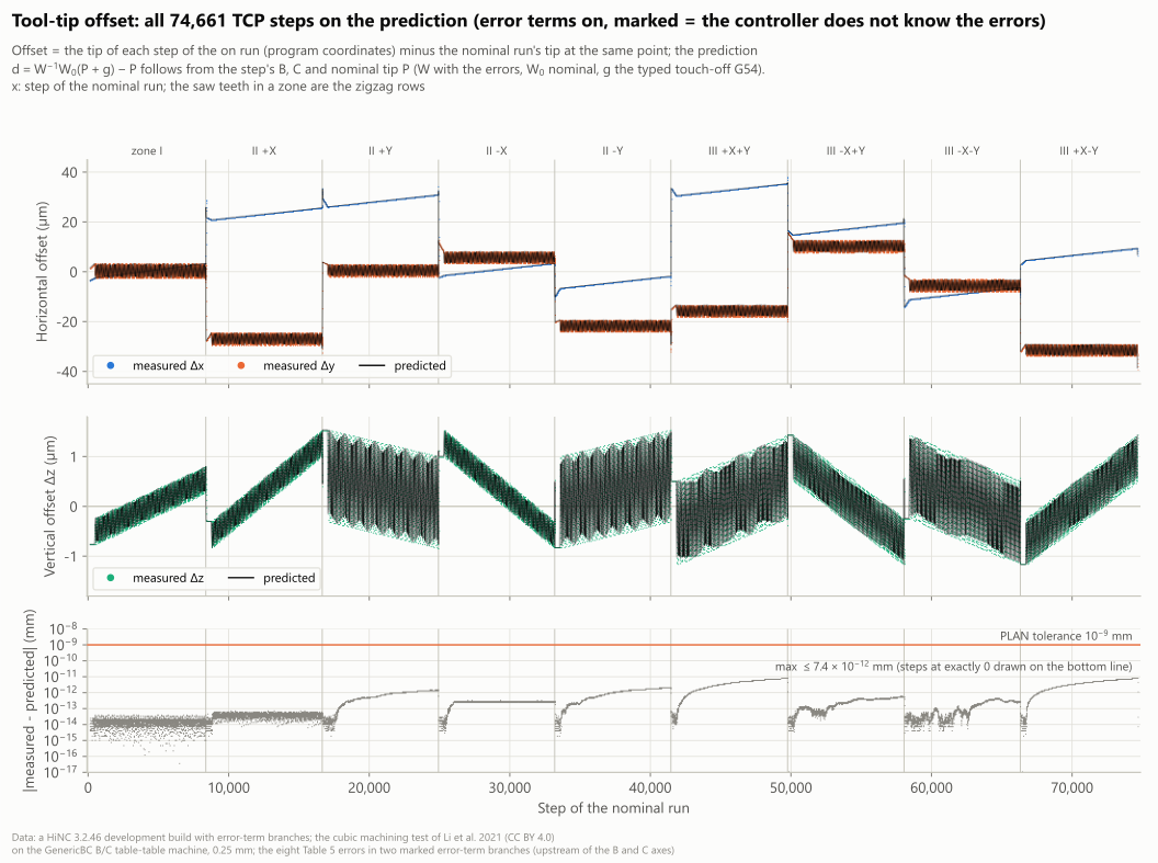
Error terms on, marked (the controller does not know the errors): the tool-tip offset of the 74,661 TCP steps (the on run minus the nominal run at the same point, program coordinates) against the prediction d = W⁻¹W₀(P + g) − P. Up to 40.5 µm sideways (on the moves away from the face, the tip up to z 60 mm, where the angular errors have a longer lever; 35.0 µm on the steps at the face) and 1.52 µm vertically; every step within 7.4 × 10⁻¹² mm of the prediction. The sawtooth within each zone is the zigzag's rows going back and forth. A HiNC 3.2.46 development build with error-term branches, 0.25 mm.
The 143 steps outside the TCP section (as many in every run): the plan's per-step formula is a
controller's solving the nominal chain step by step under TCP (x = R_B R_C (P + g)), yet criteria 5 and 6
say “every step”. The TCP section here is lines 12–2935, after G43.4 took effect and the approach from the
tool-change position finished, and before G49. Line 11, the approach, runs under G43.4 too, but its
machine difference blends in a straight line from 0 to the first TCP value, so it is listed with the tool
change and the moves after G49. Each of the three pieces follows its own rule, and every step still
satisfies the chain (tip = W⁻¹(machine tip), within 1.8 × 10⁻¹³ mm).
| Piece | Line | Steps | The on run's machine difference | Residual of the rule |
|---|---|---|---|---|
| Tool change | line 7, T1 M06 |
1 | 0: a fixed machine position | 0 |
| Approach | line 11, the first rapid after G43.4 |
119 | blends in a straight line from 0 to the first TCP value (11.700, −10.996, −0.647) µm | ≤ 9.2 × 10⁻¹⁴ mm |
After G49 |
line 2937, G00 Z200. B0. C0. |
23 | only Z, blending in a straight line from −8.585 to −0.647 µm; X and Y stay at (−13.575, −0.497) µm | ≤ 7.2 × 10⁻¹⁵ mm |
On eLp's and eLm's approach, the machine Z blends in a straight line from 0 to ±0.010 mm, so criterion 5's
“Z ±0.010 mm at every step once G43.4 is in effect” misses there by up to 0.00992 mm on those 119 steps.
The zone heights: the ball paths' face height change on the prediction
Criteria 8–10 read the Diff's box mean: the signed distance of every vertex of the cut to the nominal cut, averaged inside the box. That quantity reads the ridges one ball per step leaves (dilemma 6). To see how far the errors raise or lower a face, the face height change was computed from the per-step series as well:
- each step's tip in both runs, through its own chain, turned into the ball centre (ball centre = tip + r·a′);
- the continuous envelope the ball sweeps along each row, the face of the ball path;
- the mean difference of the two runs' faces, densely sampled inside the measurement box.
This is the quantity the plan predicted. The check script computed it once on the shared server and the analysis recomputed it; the two agree within 5 × 10⁻⁷ µm. Positive = the on run's face stands higher than the nominal (material left, blue in the Diff).
| Zone | Vertices in the box | The plan's box prediction | Face height change | Against zone I | Fixed-place model | One ball per step: area mean | Diff box mean (vertices) | Rows of 48↔49 |
|---|---|---|---|---|---|---|---|---|
| I | 4,088 | −0.00001 | −0.0002 | 0 | +0.00001 | +0.0007 | −0.054 | 0 |
| II +X | 2,753 | +0.4291 | +0.4326 | +0.4329 | +0.4330 | +0.435 | +0.080 | 0 |
| II +Y | 2,802 | +0.4298 | +0.4328 | +0.4331 | +0.4330 | +0.431 | +0.151 | 0 |
| II −X | 2,883 | +0.4324 | +0.4329 | +0.4331 | +0.4330 | +0.416 | +0.313 | 7 |
| II −Y | 2,817 | +0.4318 | +0.4327 | +0.4330 | +0.4330 | +0.432 | +0.239 | 0 |
| III +X+Y | 2,263 | +0.2297 | +0.2337 | +0.2340 | +0.2340 | +0.151 | −0.079 | 54 |
| III −X+Y | 2,318 | +0.2321 | +0.2340 | +0.2342 | +0.2340 | −0.204 | −0.507 | 58 |
| III −X−Y | 2,363 | +0.2335 | +0.2339 | +0.2341 | +0.2340 | −0.240 | −0.602 | 67 |
| III +X−Y | 2,299 | +0.2311 | +0.2337 | +0.2339 | +0.2340 | +0.390 | +0.223 | 70 |
µm, except the vertices and rows. The measurement boxes: zone I 14 × 14 mm, zones II 11 × 14 mm, zones III 11 × 11 mm (each 1 mm in from its neighbours). “Rows of 48↔49” counts the rows of the zone with another step count in the two runs (161 rows per zone).
- The face height change meets the plan's box prediction within 0.0040 µm, and within 0.0043 µm against zone I.
- The four zones of a kind are alike: measured spreads 0.00026 / 0.00026 µm. The plan's box predictions have spreads of their own, 0.0033 / 0.0037 µm: they follow “the ball whose nominal lowest point is at the box centre”, the measurement the face “at the box centre”. Every face is also tilted (next section) and every ball slides on it by up to 35.0 µm, so the two differ by up to 0.0043 µm. The same chain evaluated at a fixed place, the “fixed-place model”, gives +0.43296 µm for all four zones II and +0.23398 µm for all four zones III, and the measurement lies within 0.0004 µm of it (dilemma 7).
- The Diff's box means, −0.602 to +0.313 µm, sit up to 0.836 µm off the face height change (zone III −X−Y); why is told below.
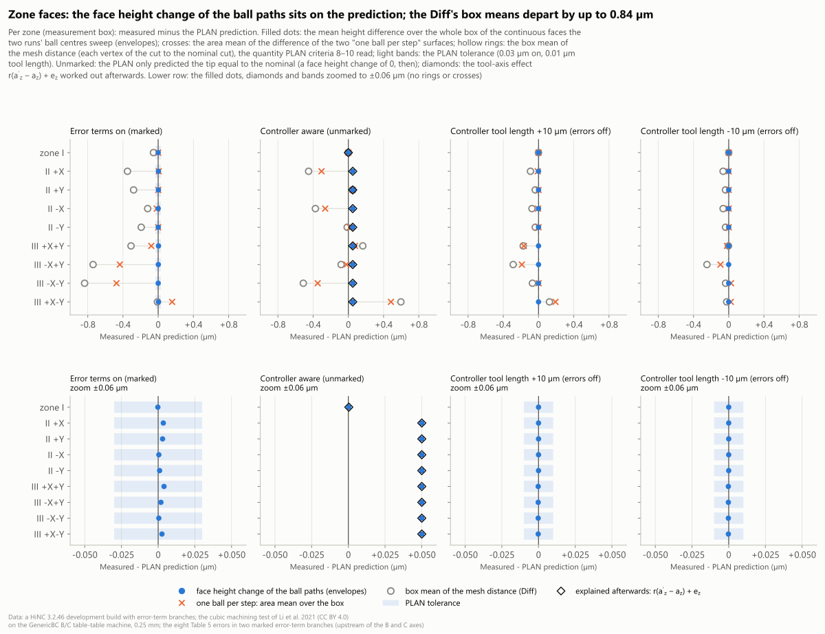
Measured minus the plan's prediction for the nine zones, four runs. Filled dots: the mean height difference over the whole measurement box of the continuous faces the two runs' ball paths sweep (on within 0.0040 µm, tool length ±10 µm within 0.00024 µm); crosses: the area mean of the difference of the two “one ball per step” surfaces; hollow rings: the box mean of the mesh distance, the quantity criteria 8–10 read, up to 0.84 µm off the face height change in the on run. Unmarked: the plan only predicted the tip equal to the nominal (a face height change of 0, then), measured +0.050 µm, the diamonds the explanation worked out afterwards, r(a′z − az) + e_z. The lower row zooms the filled dots to ±0.06 µm, where the plan's tolerance bands (0.03 µm on, 0.01 µm tool length) become visible. Both signs weighted alike, symmetric horizontal axes. A HiNC 3.2.46 development build with error-term branches, 0.25 mm.
Which error does it: each of the eight errors alone, with its own touch-off work offset, from the prediction script before the first play (at the centroid of each zone's part inside the article's 40 × 40 mm window, against zone I, µm):
| Error (Table 5) | Value | Zones II | Zones III | Where it comes from (derived) |
|---|---|---|---|---|
| δx_BY | 2.0 µm | +1.000 | +1.000 | 2.0 µm × sin 30° |
| δy_BY | −11.0 µm | 0.000 | 0.000 | |
| δz_BY | −0.647 µm | −0.087 | −0.087 | −0.647 µm × (1 − cos 30°) |
| α_BY | 0.0017° | +0.000003 | +0.000004 | |
| β_BY | 0.0019° | −0.464 | −0.657 | the zone centre's distance from the pivot (14 / 19.8 mm) times 0.0019° (33.2 µrad) |
| γ_BY | 0.0210° | −0.0005 | −0.0006 | |
| α_CB | −0.0054° | 0.000 | 0.000 | |
| δx_CB | 9.7 µm | 0.000 | 0.000 | |
| All eight together (mean of four zones) | +0.447 | +0.255 | the sum of the eight alone differs by 0.003 µm or less (cross terms) |
With the part centred on the C axis and its face at the pivot's height, α_BY, γ_BY, δy_BY, α_CB and δx_CB only move the part sideways or have no lever. Without a touch-off, zone I itself would stand +0.648 µm high (mostly δz_BY: the part sits 0.647 µm low, and the tool cuts that much less); the typed touch-off takes it out, and the heights against zone I hardly change (+0.447 / +0.255 µm without one as well).
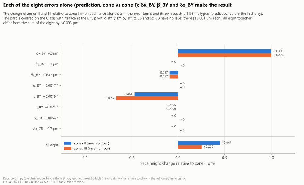
The change of zones II and III against zone I with each Table 5 error alone in the error terms (each with its own touch-off work offset; the prediction script before the first play, at the centroid of each zone's measured part): δx_BY +1.000, β_BY −0.464 / −0.657, δz_BY −0.087 µm, the other five 0.001 µm or less each; all eight together +0.447 / +0.255 µm. The measurement boxes are centred further out (x or y at ±14.5 mm against ±14 mm), where the tilted face stands lower, so their predictions are +0.4291 to +0.4324 / +0.2297 to +0.2335 µm.
Every zone's face tilts as well
The errors do not only raise or lower each zone's face; they tilt it. Plotted point by point inside the nine measurement boxes, the on run's face height change is a sloping plane in every box:
- From a box's centre to its farthest corners the face rises and falls by ±0.68 (zone I), ±0.98–0.99 (zones II) and ±0.89 µm (zones III); from one corner to the opposite one by up to 1.97 µm.
- The measured slopes lie within 0.0003 µm/mm (0.3 µrad) of the model's.
- The box mean is the value at the box centre, so the zone means the article reads do not show the tilt.
γ_BY and α_CB, which tilt zones II and III most, do not move the zone means (zone I's tilt comes mostly from α_CB; γ_BY does not tilt zone I). With each error alone, the rise from a box's centre to its farthest corner (model, µm):
| Error | Zone I | Zones II | Zones III | Effect on the zone mean |
|---|---|---|---|---|
| α_BY | ±0.21 | ±0.18 | ±0.20 | ≤ 0.0000042 |
| β_BY | ±0.23 | ±0.18 | ±0.26 | −0.464 / −0.657 |
| γ_BY | 0 | ±1.28 | ±1.43 | ≤ 0.0007 |
| α_CB | ±0.66 | ±0.66 | ±0.73 | 0 |
| All eight together (model) | ±0.68 | ±0.99 | ±0.89 | |
| All eight together (measured, plane fit) | ±0.68 | ±0.98–0.99 | ±0.89 |
δx_BY, δy_BY, δz_BY and δx_CB only translate; they do not tilt the faces.
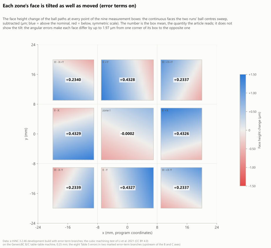
Error terms on: the face height change at every point of the nine measurement boxes (the continuous faces of the two runs' ball paths subtracted, µm; blue = above the nominal, red = below, symmetric scale). The number at a box centre is the box mean, the quantity the article reads; but the angular errors also tilt every face, by up to 1.97 µm from one corner of a box to the opposite one (centre to farthest corner: zone I ±0.68, zones II ±0.98–0.99, zones III ±0.89 µm), within 0.0003 µm/mm of the predicted slopes. A HiNC 3.2.46 development build with error-term branches, 0.25 mm.
The tool length: the controller's tool 10 µm too long or too short
With the controller's tool length 10 µm longer than the real one (eLp), TCP lifts the spindle by 10 µm: every TCP step's machine Z is +0.010 mm higher, and X, Y, B and C stay (on this table-table machine the tool axis is machine +Z). The real tip stops eL·a short of the program point along the tool axis: zone I keeps 10 µm, a zone tilted 30° only 10 cos 30° = 8.660 µm, so the tilted zones stand 1.340 µm lower than zone I. 10 µm short (eLm) turns it over.
| Zone I | Four zones II | Four zones III | Against zone I (II / III) | |
|---|---|---|---|---|
| eLp: face height change | +10.0000 | +8.6603 | +8.6600 | −1.3397 / −1.3400 |
| eLm: face height change | −10.0000 | −8.6603 | −8.6605 | +1.3397 / +1.3395 |
| Predicted ±eL·cos B | ±10.0000 | ±8.6603 | ±8.6603 | ∓1.3397 |
| eLp: Diff box mean | +9.999 | +8.569 to +8.623 | +8.372 to +8.784 | −1.627 to −1.215 (the eight tilted zones) |
| eLm: Diff box mean | −10.000 | −8.724 to −8.697 | −8.907 to −8.663 | +1.092 to +1.337 (the eight tilted zones) |
µm. The face height change meets the prediction within 0.00024 µm; the Diff's box means spread because these two runs have rows of 48↔49 too (176 rows in eLp, 226 in eLm) and read the ridges again (dilemmas 4 and 6). The article's values are set beside them under “against the article”.
The whole block from above (+Z; +X to the right, +Y up), alternating in place between “controller tool length +10 µm” and “controller tool length −10 µm”. +10 µm: all blue (material left), zone I darker (+10.00 µm), the tilted zones lighter (+8.66 µm), dotted ridges on the rows with another step count; −10 µm: all orange (cut too deep), zone I darker (−10.00 µm), the tilted zones lighter (−8.66 µm). The step between the two shades is the 1.34 µm. Diff colour range ±0.012 mm (red = cut too deep, blue = material left, green = 0, both signs weighted alike); 0.25 mm; a HiNC 3.2.46 development build with error-term branches.
An oblique view (from above the −X −Y corner; the far corner is out of the frame), alternating in place between “controller tool length +10 µm” and “−10 µm”: zone I one shade darker than the tilted zones; the sides were not cut and are green. Colour range ±0.012 mm, grid and build as above.
The controller that knows the errors (unmarked): the tip 5.85 nm off, the tilted faces 0.050 µm high
This run cleared both marks with the switch still on: the machine is still the one with the errors, but the controller's model now holds them, as a controller with calibrated kinematics would. It typed in the same touch-off g as the on run.
- The tip: every TCP step sits at P + e, e = (4.010, 4.246, 0.323) nm, |e| = 5.85 nm. It is a constant, varying by at most 6.6 × 10⁻¹² mm over the section, and it equals (I − R0⁻¹)g within 5.4 × 10⁻¹² mm, R0 being the two errors' rotations combined at B = C = 0. In words: the typed G54 is added in table coordinates without R0 turned back out. This is a second-order term, of the order of |g| × 0.021154° = 5.93 nm. The plan wrote the tip equal to the nominal (criterion 6, within 1 × 10⁻⁹ mm); that half failed.
- The tilted zones' faces stand +0.0500 µm high (the eight tilted zones +0.049985 to +0.050065 µm), zone
I +0.0002 µm. The B and C under
G43.4are the angles the program commands: the calibrated controller puts the tip back on the program point, but the tool's direction on the part still follows those angles turned through the errors, a′ rather than a. Ball centre = tip + r·a′, so the ball's lowest point rises or falls by r(a′z − az). Through the prediction script's chain: on a tilted zone e_z 0.0003 + r(a′z − az) 0.0497 = 0.0501 µm, the same on every tilted zone and at every C; zone I 0.0003 µm. - Machine coordinates: the unmarked run's X, Y, Z differ from the nominal run's (G54 zero) at the same point by W(P + e) − W₀P, up to (15.6, 25.2, 6.5) µm (within 5.4 × 10⁻¹² mm of the model). The controller unaware of the errors (marked, the same g) differs by a constant R_B R_C g per zone, up to (16.0, 16.1, 8.6) µm. The difference between the two is where calibrated kinematics puts the linear axes; B and C are the same in both runs.
- The cut faces: in the Diff, zone I and zone II +Y, where every row has the same step count in both runs, are all green; zone II −Y has only 4 dotted rows of ridges; the rows whose step counts differ between the two runs (367 rows between the unmarked and the nominal run) are speckled.
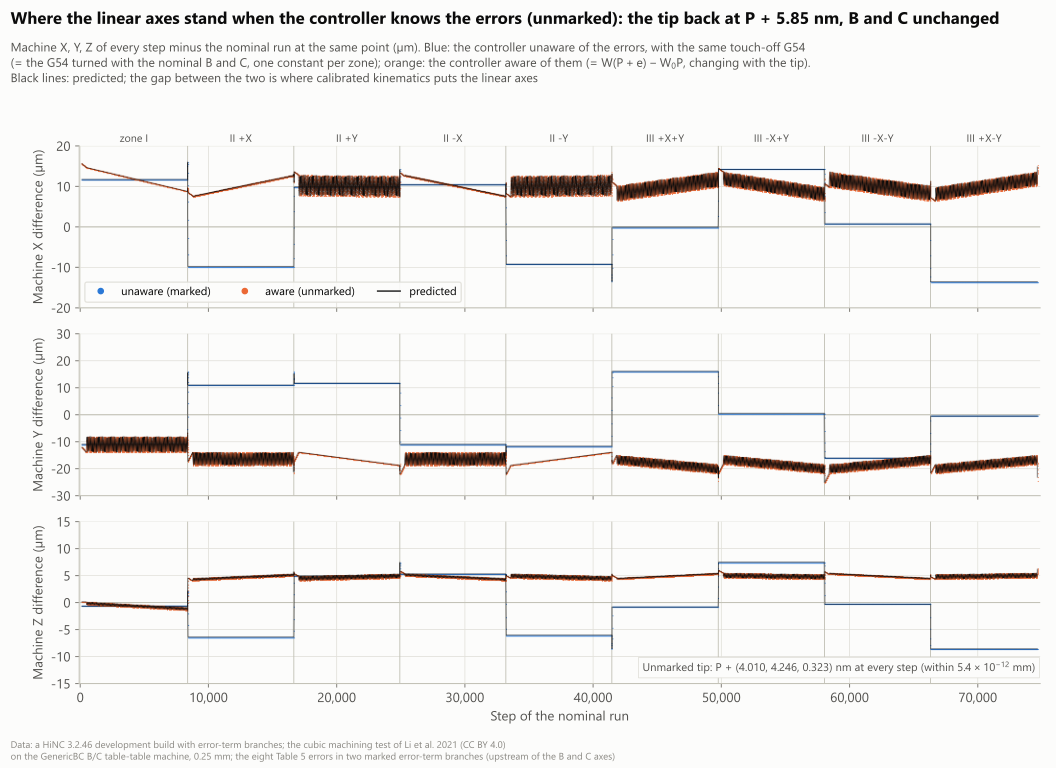
Where the linear axes stand when the controller knows the errors (unmarked). Machine X, Y, Z of every step minus the nominal run at the same point: the controller unaware of them, with the same touch-off G54 typed in (marked), is one constant per zone, the G54 turned with the nominal B and C; the aware controller is W(P + e) − W₀P, up to (15.6, 25.2, 6.5) µm, within 5.4 × 10⁻¹² mm of the prediction. B and C are unchanged, and the tip is back at P + (4.010, 4.246, 0.323) nm. Dots measured, black lines predicted. A HiNC 3.2.46 development build with error-term branches.
The whole block from above (+Z; +X to the right, +Y up), one camera alternating between “controller unaware (marked)” and "controller aware (unmarked)". Unmarked: zone I and zone II +Y all green, zone II −Y only 4 dotted rows of ridges; in zones II −X and +X (66 and 70 rows) and the zones III (31–89 rows each), the rows whose step counts differ between the two runs are speckled. The tip is only 5.85 nm off and the tilted faces only +0.050 µm; what the picture still shows is ridges of steps falling out of step. Marked: as in the on and off pair below. Diff colour range ±0.003 mm (red = cut too deep, blue = material left, green = 0, both signs weighted alike); 0.25 mm; a HiNC 3.2.46 development build with error-term branches.
A closer top view (zone I in the middle, zones II −X and +X left and right, parts of zones II +Y, −Y and the four zones III above and below), alternating in place between “marked” and “unmarked”. In the unmarked frame zone I in the middle is all green, the dotted rows of ridges below it are zone II −Y's rows with another step count, and zones II ±X left and right are speckled; the marked frame shows the gradient and the stripes. The white glow is the viewer's light. Colour range, grid and build as above.
An oblique view (from above the −X −Y corner; the far corner is out of the frame), alternating in place between “marked” and “unmarked”: unmarked mostly green, only the speckles of the rows with another step count; marked the zones' stripes, speckles and gradients. Colour range, grid and build as above.
Why the Diff's box means are not the face height
- One ball per step. With Feed Per Cycle motion, HiNC puts the tool at each step's pose and does not sweep it between steps. The cut's vertices lie on the union of the balls at the steps' poses: in every box, at least 99.8 % of the vertices lie within 0.0001 µm of that union.
- Ridges and scallops. Two neighbouring steps on a row are 1/3 mm apart and leave a 4.63 µm ridge between their balls (4.45 µm on a row of 49 steps); neighbouring rows are 0.1 mm apart and leave a 0.42 µm scallop (derived: r − √(r² − (s/2)²), r = 3 mm, s the step or the row spacing).
- The two runs' balls land at different places. On a row of 48 steps against 49, the two runs' balls sit at different places along the row; in the on run, each tilted zone's balls also moved along X row by row (0.6–32.5 µm on average per zone, at most 35.0 µm). At the vertices inside the boxes, the two ridged surfaces differ by between −5.19 and +4.99 µm (on).
- The Diff's box mean is a mean over vertices. It equals the difference of the two unions at the same vertices (on within 0.020 µm, the other runs within 0.00051 µm), and the vertices do not sample that ridged surface evenly.
The box means broken down (four runs, 36 boxes):
| Boxes | One ball per step, area mean − face height change | Diff box mean (vertices) − face height change | |
|---|---|---|---|
| Boxes whose rows have the same step count in both runs | 12 | ≤ 0.0027 µm (sampling standard error ≤ 0.0033 µm) | −0.352 to +0.0003 µm |
| Boxes with rows of 48↔49 | 24 | −0.474 to +0.434 µm | −0.836 to +0.547 µm |
- Where every row has the same step count in both runs, the two ridged surfaces' area mean equals the face height change.
- Where rows swap 48↔49, even the area mean is off: those rows' ridges stand at other heights and fall out of step with the neighbouring rows.
- The vertex mean is off again on top of that, by up to −0.352 µm even in a box with the same step counts (on, zone II +X, where every ball moved 22.8 µm along its row on average).
So criteria 8–10 failed because of the step-by-step simulation (balls not swept, rows rounded to 48 or 49 steps) and the vertex sampling, not because the error terms or the predictions were wrong. The face height computation was checked on its own as well: a full computation over every ball and the fast one used here (a 0.6 mm window, the 24 nearest balls) agree point by point on 2,400 points per run and 1,500 points over the whole face, within 4.5 × 10⁻¹⁶ mm.
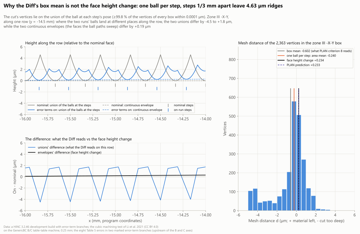
Why the Diff's box mean is not the face height change: the cut's vertices lie on the union of the ball at each step's pose (in every box at least 99.8 % of them within 0.0001 µm), and balls 1/3 mm apart leave 4.63 µm ridges. Along y = −14.5 mm in zone III −X−Y the two runs' balls land at different places, so the unions differ by −4.5 to +1.8 µm while the envelopes differ by only +0.19 µm. Right: the mesh distance of the box's 2,363 vertices, mean −0.602, the area mean of one ball per step −0.240, the face height change +0.234 and the prediction +0.233 µm. Positive = material left, negative = cut too deep, a symmetric horizontal axis. A HiNC 3.2.46 development build with error-term branches, 0.25 mm.
The control run and the Diff pictures
- The control run is the nominal played again: its per-step series (tips, machine coordinates, program lines) are the nominal's, and so is its count of steps touching the material (70,307); its cut's 57,523 vertices lie within 5.0 × 10⁻¹⁰ mm of the nominal cut (at most 4.96 × 10⁻¹⁰ mm). This is the noise floor.
- The whole part's extremes (on against nominal): −5.25 to +4.99 µm on the cut face, within 0.00051 µm of the extremes the step-pose model reads on the face; below the 6 µm threshold, they were not checked by exact distance. At the block's edge (|x| or |y| = 24 mm), 185 vertices read 6.02–8.57 µm: real distances by the exact check, yet the step-pose model reads only +0.02 to +1.62 µm at those vertices. The two meshes represent the 90° edge differently; it is not a deviation of the face (dilemma 9).
- The two uncut side faces: 3 vertices each, d = 0.
The three pictures below alternate in place at one camera between the error terms on (marked) and off (the control). They put the run's recorded stock back on the canvas with its Diff, without replaying. The canvas captures carry no interface text: the English and the Chinese interface captured the same canvas byte for byte, and only the label at the upper left changes with the language; the Df colour bar sits in a corner.
The whole block from above (+Z; +X to the right, +Y up), one camera alternating between “error terms on” and “error terms off”. On: zone I only a gentle gradient (the errors tilt its face, ±0.68 µm across the box); the balls of zones II +X and +Y moved 23–28 µm along the rows on average, a stripe every 1/3 mm; zone II −Y (4.6 µm on average) faint stripes; zone II −X (0.6 µm) a gradient with a row of dots along its lower edge, its 7 rows with another step count; in each zone III 54–70 rows took 48 steps in one run and 49 in the other: speckles. Stripes and dots reach about ±5 µm, all of them ridges of one ball per step falling out of step, beyond the ±3 µm colour range and saturated. Off: all green. Diff colour range ±0.003 mm (red = cut too deep, blue = material left, green = 0, both signs weighted alike); 0.25 mm; a HiNC 3.2.46 development build with error-term branches.
A closer top view (zone I in the middle, zones II −X and +X left and right, parts of zones II +Y, −Y and the four zones III above and below), alternating in place between “error terms on” and “error terms off”. On: zone I in the middle a gradient, zone II +X on the right striped, zone II −X on the left a gradient with a row of dots along its lower edge (its 7 rows with another step count), zone II +Y's stripes above and zone II −Y's gradient below, the zones III's speckles in the corners; the white glow is the viewer's light. Off: all green. Colour range, grid and build as above.
An oblique view (from above the −X −Y corner; the far corner is out of the frame), alternating in place between “error terms on” and “error terms off”. On: the red and yellow speckles of zone III −X−Y near the camera, which make its box mean of −0.602 µm; the sides were not cut and are green. Off: all green. Colour range, grid and build as above.
Diff--Stats of the eight runs with a Diff
| Run | Reported leaves | Surface leaves before comparison | Expanded on demand | New nodes | NaN leaves | Measured wires | Unmeasured wires | Target triangles |
|---|---|---|---|---|---|---|---|---|
| f-control | 65,359 | 58,935 | 2,768 | 9,192 | 0 | 187,378 | 173 | 113,502 |
| f-on | 54,829 | 47,508 | 3,076 | 10,397 | 3 | 187,085 | 9,639 | 113,502 |
| f-unmarked | 48,116 | 39,500 | 3,508 | 12,124 | 0 | 188,062 | 346 | 113,502 |
| f-eLp | 48,116 | 39,500 | 3,508 | 12,124 | 0 | 188,404 | 4 | 113,502 |
| f-eLm | 46,832 | 40,408 | 2,768 | 9,192 | 0 | 184,304 | 0 | 113,502 |
| t-control | 4,752 | 4,752 | 0 | 0 | 0 | 17,408 | 3 | 8,866 |
| t-on | 5,096 | 4,955 | 51 | 192 | 3 | 17,948 | 1,160 | 8,866 |
| t-unmarked | 4,820 | 4,364 | 154 | 610 | 4 | 18,424 | 6 | 8,866 |
- The nominal runs make no Diff.
- The on run has 3 NaN leaves and 9,639 unmeasured wires (the control 0 and 173), with no positions in the records; no number on this page uses the Diff's leaves, only the exported cuts and the per-step series.
- The unmarked and the eLp run share their first four numbers, and the control and the eLm run their third and fourth; why was not looked into.
Against the article
| Zone (the article's name) | Here: the eight Table 5 errors, face height change against zone I | Article, Fig. 11a (simulated) | Article, Fig. 7a (measured) | Fig. 7a − Fig. 11a |
|---|---|---|---|---|
| I | 0 | 0 | 0 | 0 |
| II +X (II-3) | +0.433 | −0.1 | +4.5 | +4.6 |
| II +Y (II-4) | +0.433 | +0.1 | +4.4 | +4.3 |
| II −X (II-1) | +0.433 | −0.8 | +5.7 | +6.5 |
| II −Y (II-2) | +0.433 | −1.1 | +5.9 | +7.0 |
| III +X+Y (III-3) | +0.234 | +0.9 | +6.1 | +5.2 |
| III −X+Y (III-4) | +0.234 | +0.1 | +5.8 | +5.7 |
| III −X−Y (III-1) | +0.234 | −1.4 | +4.9 | +6.3 |
| III +X−Y (III-2) | +0.234 | −0.6 | +5.7 | +6.3 |
| Zone | Here: tool length +10 µm | Article, Table 6 (simulated, +10 µm) | Article, Table 3 (measured, +10 µm) | Here: tool length −10 µm | Article, Table 6 (−10 µm) | Article, Table 3 (−10 µm) |
|---|---|---|---|---|---|---|
| II +X (II-3) | −1.340 | −1.3 | −2.4 | +1.340 | +1.3 | +2.0 |
| II +Y (II-4) | −1.340 | −1.3 | −3.6 | +1.340 | +1.4 | +1.0 |
| II −X (II-1) | −1.340 | −1.3 | −3.7 | +1.340 | +1.3 | −0.5 |
| II −Y (II-2) | −1.340 | −1.3 | −4.0 | +1.340 | +1.4 | +0.8 |
| III +X+Y (III-3) | −1.340 | −1.3 | −2.9 | +1.340 | +1.3 | +1.5 |
| III −X+Y (III-4) | −1.340 | −1.3 | −2.0 | +1.340 | +1.3 | +1.5 |
| III −X−Y (III-1) | −1.340 | −1.3 | −2.2 | +1.340 | +1.4 | +2.9 |
| III +X−Y (III-2) | −1.340 | −1.3 | −2.4 | +1.340 | +1.4 | +1.1 |
µm, all against zone I. The article's values are the numbers printed in its figures and tables (the cells of Figs. 7 and 11 print mm, converted to µm here). Eq. (2)'s (1 − cos 30°)·eL = 1.3397 µm.
- The simulation (Fig. 11a): the article −1.4 to +0.9 µm, every zone different; here +0.234 to +0.433 µm, the four zones of a kind alike. The difference lies in where the part sits against the B and C axes and in the point the angular errors turn about, neither of which the article gives: here the part's centre is on the C axis and its top face at the height where the two axes cross, and five of the eight errors have no lever (dilemma 1). Where the article's part sat is not known, so the two compare only qualitatively.
- The signs (dilemma 2): with all eight values reversed, as a literal reading of the article's eq. (4) puts them, the zone heights against zone I turn over: zones II −0.452 to −0.449, zones III −0.260 to −0.257 µm. Neither reading matches Fig. 11a's pattern, and this page does not claim the article's sign.
- The measurement (Fig. 7a): +4.4 to +6.1 µm; less the article's own simulation, +4.3 to +7.0 µm remain in each zone. In Section 5 the authors measured the ball end mill's profile differing by about 4 µm between 0° and 30° (Fig. 13) and explain this difference of about 5 µm with it. The model's ball is perfect; that share is not in this case.
- The tool length: here every tilted zone is −1.3397 to −1.3400 µm with the tool 10 µm long and +1.3395 to +1.3397 µm with it 10 µm short, as eq. (2) says (1.3397 µm); the article's Table 6 gives −1.3 (+10 µm, every zone) and +1.3 or +1.4 (−10 µm, four zones at +1.4). The article's measured changes (Table 3) are −4.0 to −2.0 and −0.5 to +2.9 µm; the authors say other factors are also at work.
- The article's zone names: Tables 3 and 6 name ZONE II-1 to III-4 without saying which zone each is. Matching Table 3 with the differences between Fig. 7's zones (b minus a, c minus a), the eight numbers fit only one way: II-1 to II-4 = −X, −Y, +X, +Y, and III-1 to III-4 = −X−Y, +X−Y, +X+Y, −X+Y (the figures' x to the right, y up). With the same names, Table 6 equals Fig. 11 (b) and (c) minus (a). Table 6's title says “experiment”, but its text is Section 4.3's simulation.
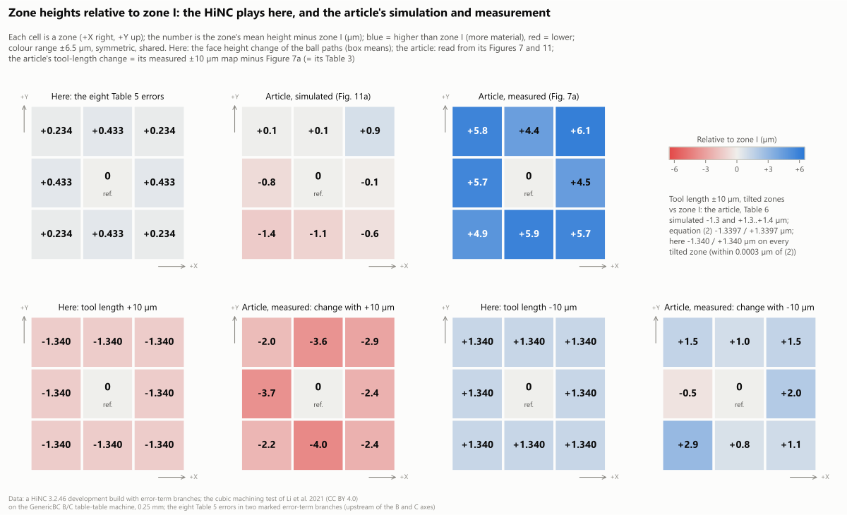
Zone heights against zone I (µm), 3 × 3 side by side: here, the eight Table 5 errors give +0.234 to +0.433, the four zones of a kind alike; the article's simulation (Fig. 11a) −1.4 to +0.9, every zone different; its measurement (Fig. 7a) +4.4 to +6.1. Tool length ±10 µm: here −1.340 / +1.340 on every tilted zone, the article's measured changes (Table 3) −4.0 to −2.0 and −0.5 to +2.9. Blue = higher than zone I, red = lower, a symmetric colour range shared by all. The values here are the face height change of the ball paths (box means). The article's numbers are from Li et al., J. Manuf. Mater. Process. 5, 51 (2021), Figs. 7 and 11 and Tables 3 and 6, CC BY 4.0. A HiNC 3.2.46 development build with error-term branches.
The holder
The front view at the top of the page and the isometric view below both put the on run's recorded stock
back on the canvas and play the parking program NC/pose-t1.nc under the typed G54: T1 tilted 30° at B30
C180, the tip at z 2.4019 mm, the ball's lowest point 2 mm above the centre of zone II +X. The front view
shows the cutter, the neck, the shank and the shrink-fit holder (the top of the SK40 body is cut off by the
frame); the isometric view looks almost along the tool axis, and the SK40 body hides the cutter. All ten
runs' projects had collision detection on, and no collision message came.
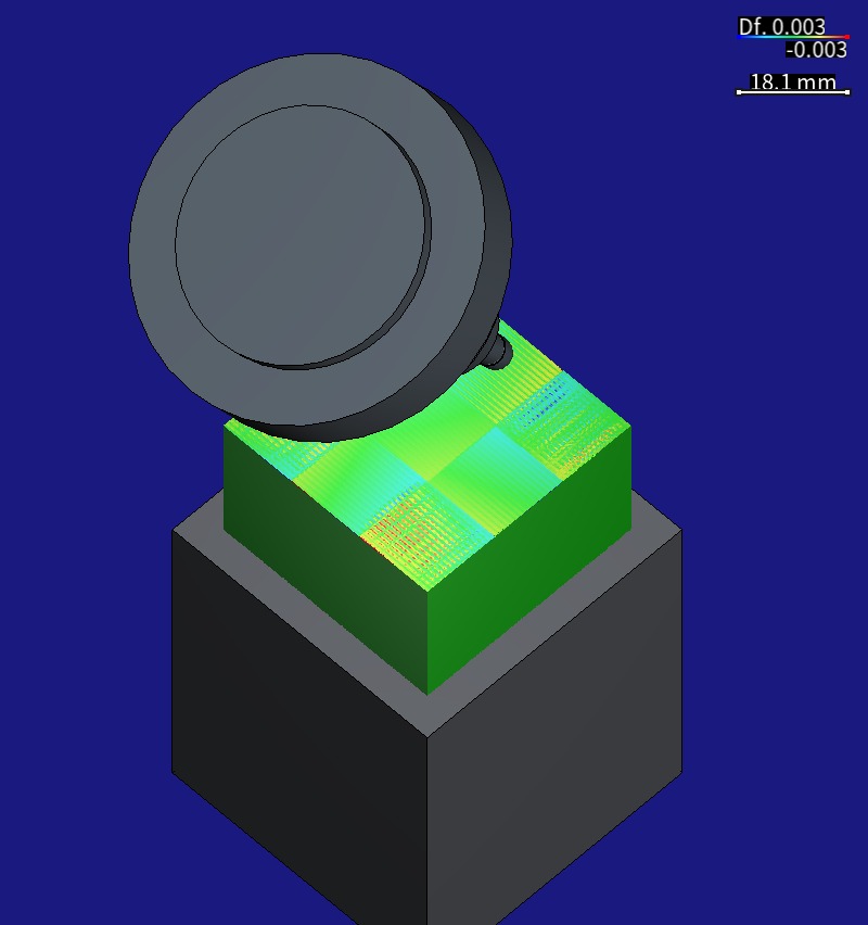
The same parking pose in an isometric view (no cutting). From this angle, almost along the tool axis, the disc of the SK40 body hides the ball end mill, the neck, the shank and the slim shrink-fit neck, a short piece of which shows at the disc's lower right; the whole cutter and holder show in the front view at the top of the page. The on run's Diff lies over the part, colour range ±0.003 mm (red = cut too deep, blue = material left, green = 0, both signs weighted alike): the stripes and dots of the nine zones on the top face are told under the control run and the Diff pictures; the sides were not cut and are green. 0.25 mm; a HiNC 3.2.46 development build with error-term branches.
What the runs cost
All runs used private instances of a HiNC 3.2.46 development build with error-term branches on the shared 32-thread server, one run at a time, in the order played.
| Play | Grid | Switch / marks | Steps | Wall time | Peak memory (VmHWM) |
|---|---|---|---|---|---|
| t-nominal | 1 mm | off | 74,690 | 90.1 s | 1.332 GiB |
| t-on | 1 mm | on / marked | 74,804 | 90.1 s | 1.344 GiB |
| t-control | 1 mm | off | 74,690 | 90.1 s | 1.339 GiB |
| t-unmarked | 1 mm | on / cleared | 74,821 | 90.1 s | 1.275 GiB |
| f-nominal | 0.25 mm | off | 74,690 | 90.1 s | 1.445 GiB |
| f-control | 0.25 mm | off | 74,690 | 90.1 s | 1.460 GiB |
| f-unmarked | 0.25 mm | on / cleared | 74,821 | 90.1 s | 1.495 GiB |
| f-eLp | 0.25 mm | off, tool length +10 µm | 74,722 | 90.1 s | 1.506 GiB |
| f-eLm | 0.25 mm | off, tool length −10 µm | 74,712 | 85.1 s | 1.429 GiB |
| f-on (the replayed run) | 0.25 mm | on / marked | 74,804 | 90.1 s | 1.435 GiB |
- Peak memory: the instance was restarted before every run, so each VmHWM is that run's own peak, the Diff, the export and the stock record included (GiB = bytes ÷ 2³⁰). The whole-part runs with a Diff peak −0.016 to +0.061 GiB from the nominal run, which makes no Diff: the Diff's cost does not show.
- Wall time runs from the request to play to the first poll that read
Finished; the poll comes every 5 s, and nine of the ten runs fell on the same poll, 90.1 s. The start and end time stamps (to the second) give 87–93 s, covering the play, the cut's export, the Diff and the records. - The times (2026-10-07): trimmed runs 04:44:15–04:50:34, whole-part runs 04:58:39–05:08:04, the on run played again for the evidence script 05:18:49–05:20:21.
- The grid: from 1 mm to 0.25 mm the time per run stayed the same, and the peak memory went from 1.275–1.344 GiB to 1.429–1.506 GiB.
- The base's 1 mm rough run: 74,690 steps, 90 s; the program's cycle time is 12 min 15 s.
- The analysis recomputes every number from the records in about 6 minutes on an ordinary desktop, 1–5 minutes with its cache, in under 400 MB.
What it means
For a machining engineer.
- On a five-axis machine with a B/C tilting rotary table, the eight rotary-axis errors a ball bar measured raise zones II and III of the cubic machining test by only 0.43 and 0.23 µm against zone I, with the part centred on the C axis and its top face at the height where the B and C axes cross. “Raise” follows the plan's sign convention; with the values put in as a literal reading of the article's eq. (4), the zones turn over and stand lower than zone I (dilemma 2). δx_BY alone (the B axis 2 µm off along X) gives +1.0 µm, β_BY takes 0.46–0.66 µm off and δz_BY another 0.09 µm. With the part placed elsewhere, the five errors that have no lever here would show.
- Zone means do not show the faces' tilt: the same errors make each zone differ by up to 1.97 µm from one corner of its box to the opposite one, mostly through γ_BY and α_CB, which leave the zone means almost at 0. A test that reads only zone means misses them.
- A controller tool length 10 µm off makes a zone tilted 30° stand exactly 1.34 µm off zone I (the article's eq. (2)), more than three times the zone heights these machine errors make here (0.23–0.43 µm).
- A controller with calibrated kinematics puts the tip back under
G43.4, but the tool's direction still carries the errors: with these errors the tilted zones still stand 0.05 µm high. - Most of the 4.4–6.1 µm the article measured is not the machine's geometric error: the simulation accounts for about 1 µm, and the authors attribute the rest to the cutting edge's profile.
- In HiNC, a machine's ball-bar results can go into its model, and their shape and size on your own part show before the part goes on the machine, with and without the controller knowing them.
For a teacher or a student.
- How an error becomes a tip offset through the kinematic chain, d = W⁻¹W₀(P + g) − P; why a touch-off cancels the errors only at B = C = 0; why a General Transform turns, then translates, so that the touch-off is t_B + Rot_B·t_C.
- An angular error's effect depends on the point it turns about and on the part's distance from it: β_BY in zone II is 14 mm × 0.0019° = 0.46 µm.
- When a ball end mill cuts a plane, face height = ball-centre height − r: how much the tip offset and the change of the tool's direction each contribute (d_z + r(a′z − az)).
- Why a simulation of one step per spindle revolution leaves ridges (f²/8R, 4.63 µm at 1/3 mm), and why the Diff's vertex mean reads the ridges: estimate the ridge height before writing a criterion.
For someone weighing the approach.
- Cost: a base built new from the article's numbers (stock, program, machine and tool set-up), the error-term project saved from it, and ten plays of about 90 s each at no more than 1.506 GiB.
- Predictions, written before the first play: every TCP step's tip within 7.4 × 10⁻¹² mm, the ball paths' face height within 0.004 µm, the tool-length effect within 0.00024 µm.
- What missed, written as measured: six of the twelve criteria failed as written, each cause measured and stated. The plan did not foresee how HiNC makes its steps (48 or 49 a row, no sweep), wrote only the TCP section's formulas, and its prediction for the unmarked run missed. The comparison with the article is told as it is too: this case does not explain the 4.4–6.1 µm the article measured.
Honest limits
- Error terms hold constants only. Table 5's errors are the position-independent errors a ball bar identified, and they fit; the article machine's position-dependent errors (positioning, straightness, backlash, servo) and its thermal deformation are not here (Machine Geometric Error).
- The part's place, the pivot and the signs are chosen (dilemmas 1 and 2). In this placement five of the errors have no lever, Fig. 11a's asymmetry cannot be reproduced, and the comparison with the article is only qualitative.
- The ball is perfect. The edge profile error the article measured in Section 5 (about 4 µm between 0° and 30°) is not in the model; physics is off, so neither the deflection from the cutting forces nor heat is in; the article's zero-depth pass was left out.
- The tool-length error is only the length the controller holds (as an axial wear of ∓0.010 mm would make it), not thermal growth or tool-change repeatability.
- Feed Per Cycle steps are not swept: the cut face has a ridge every 1/3 mm along a row, and the Diff's box means read the ridges (dilemma 6). The face height change is computed by this case from the per-step series; HiNC's Diff does not give it.
- The face height change and the area mean are sampled: the face height change on a dense grid inside each box (a grid centred on the box centre differs by up to 0.0004 µm), the area mean from 80,000 random points per box (standard error at most 0.0048 µm). Differences of 0.0003 µm lie within the sampling error.
- The NC writes the tip height to 0.1 µm only: the tilted zones are written at z 0.4019 (exactly 0.401924 mm), so in every run the nominal tilted zones lie 0.024 µm deeper against zone I than designed. Subtracting two runs cancels it; no difference on this page is affected.
- The face extremes were not checked exactly: the edge values beyond 6 µm rest on an exact point-to-triangle check (dilemma 9); the face extremes, −5.25 to +4.99 µm, lie below the threshold and agree with the step-pose model's within 0.00051 µm. That the edge's real distances come from the two meshes representing the 90° edge differently is an inference.
- The on run's
Diff--Statsshow 3 NaN leaves and 9,639 unmeasured wires (the control 0 and 173), with no positions in the records; no number on this page uses the Diff's leaves. - The tool's other dimensions, its stick-out and the holder are chosen; the machine is a generic B/C table-table machine, not the article's; the controller dialect, Fanuc, is chosen, as the article names none.
- The unmarked run's 5.85 nm comes from how the controller adds the typed G54 (dilemma 8). It was measured and explained through the chain, but not compared with any real controller.
- The mapping of the article's zone names is inferred: only one assignment fits Table 3 to Fig. 7's differences, and the article figures' x and y are assumed to be this program's, x to the right and y up.
- Wall times are polled every 5 s: 90.1 s means a true length between 85.1 and 90.1 s (eLm's 85.1 s, between 80.1 and 85.1 s).
What a reader can take to their own case
- Know where the part sits against the rotary axes, and about which point each angular error turns. An angular error moves the part by its angle times the lever from its pivot: with the part centred on C and its face at the height where the axes cross, five of Table 5's eight errors have no lever, and β_BY gives 14 mm × 0.0019° = 0.46 µm in zone II. Write the placement and the pivot down before predicting, and say that they are chosen.
- Settle the sign convention before the first play. An article's error definitions can be read either way; write which way they go in, and give the other reading's result as well (dilemma 2).
- Put each axis's errors where the manual puts them, an error term just before the axis's branch (where an error term may go). A General Transform turns, then translates: derive the touch-off in that order, and check it with P0 with the marks cleared before any play (dilemma 3).
- Type in the work offset a touch-off would find. P0 measures on the nominal chain (work offsets on a machine with error terms); a touch-off at B = C = 0 cancels the errors there and only there.
- Estimate the ridge height before writing a criterion on a Feed Per Cycle play. f²/8R at 1/3 mm and R 3 mm is 4.63 µm, ten to twenty times the 0.23–0.43 µm to be judged; a Diff box mean then reads the ridges. Judge such effects on the per-step series or on the ball paths' faces.
- Pair two runs by program line when their step counts differ. A row's duration rounds to 48 or 49 spindle revolutions, and changing an error term, the touch-off or the tool length flips some rows; paired by step index, everything after the first flip is misaligned (dilemma 4).
- Write a per-step formula for the section it holds in. Under
G43.4the tip formula holds from the end of the approach toG49; the tool change, the approach and the move afterG49follow their own rules (dilemma 5). - Read each face's tilt as well as its mean. Angular errors that leave the zone means alone can tilt each face by up to 1.97 µm across a box; plot the face height change point by point.
- A calibrated controller puts the tip back, not the tool's direction. Under
G43.4with the commanded B and C, the ball's lowest point still moves by r(a′z − az) (what a mark changes). - Check extreme vertex distances exactly. Here the largest readings were real distances at the block's 90° edge, where the two meshes represent the edge differently, not a cut.
- Check the build and the formulas on a coarse run first. The 1 mm runs gave the same per-step series as the 0.25 mm ones, in the same 90 s a run.
Source and licence
The test piece, the errors and the test conditions come from the article:
- Article: Zongze Li, Hiroki Ogata, Ryuta Sato, Keiichi Shirase, Shigehiko Sakamoto, “Influence of Tool
Length and Profile Errors on the Inaccuracy of Cubic-Machining Test Results”, Journal of Manufacturing
and Materials Processing 5(2), 51 (2021), MDPI, published 19 May 2021 (Kobe University; Kanazawa
Institute of Technology), https://doi.org/10.3390/jmmp5020051. Search terms if the link moves:
Influence of Tool Length and Profile Errors on the Inaccuracy of Cubic-Machining Test Results,jmmp5020051. - What this case uses of it: the machine type, the test piece and the cutting conditions (Section 2, Figs. 1 and 2, Table 1); the tool-length formulas (Section 3, eqs. (1) and (2)); the eight errors and their definitions (Section 4.3, Tables 4 and 5, Fig. 9, eqs. (4)–(11)); the measurements (Fig. 7, Table 3), the simulation (Fig. 11, Table 6) and the edge profile (Section 5, Fig. 13).
The article deposits no data ("The data presented in this study are not available."); every value comes from its text, tables and the numbers printed in its figures. The article's machine is a DMG Mori NMV 1500 DCG and its profiler a Kosaka DSF900, named here only to say where the numbers come from; this case models neither.
Licence: Creative Commons Attribution 4.0 International (CC BY 4.0). The statement on page 1 of the article:
Copyright: © 2021 by the authors. Licensee MDPI, Basel, Switzerland. This article is an open access article distributed under the terms and conditions of the Creative Commons Attribution (CC BY) license (http://creativecommons.org/licenses/by/4.0/).
CC BY 4.0 allows reproducing and adapting the article with attribution, an indication of changes and a link to the licence (Sections 2(a)(1) and 3(a)(1)), and it disclaims warranties (Section 5).
Attribution, as the case's source record gives it:
Measured data, errors and test conditions: Z. Li, H. Ogata, R. Sato, K. Shirase, S. Sakamoto, “Influence of Tool Length and Profile Errors on the Inaccuracy of Cubic-Machining Test Results”, J. Manuf. Mater. Process. 5(2), 51 (2021), https://doi.org/10.3390/jmmp5020051. © 2021 by the authors, licensee MDPI, Basel, Switzerland. Licensed CC BY 4.0 (https://creativecommons.org/licenses/by/4.0/), provided as-is without warranties. Changes: the part model, the NC program, the machine and the HiNC project are ours, built from the article's description (see “What we changed”).
What we changed (the source record's “What we changed”):
- The machine: a generic B/C table-table machine, not the article's; the finished face is set at the height where its B and C lines meet, on the C axis (program zero).
- The part: a 48 × 48 × 30 mm block with 0.1 mm to cut on top, on a 70 mm riser.
- The NC program (Fanuc,
G43.4): ours, from the article's description; the zone order, the start points and the moves between zones are chosen, and the zero-depth second pass is left out (every run is physics off). - The cutter and the holder: the article's DLC2MBR0300 gives the diameter, the flutes and the helix; the flute, neck and overall lengths, the stick-out and the holder are chosen.
- The errors: the eight values of Table 5 as two marked error terms, one just before the B axis's branch and one just before the C axis's; the point the angles turn about, where the B and C lines meet, the sign convention and the touch-off are the agent's choices.
The pictures and the charts. No figure of the article is reproduced; only the numbers it prints are used (Tables 3–6 and the values printed in the cells of Figs. 7 and 11). The pictures are HiNC captures, and the charts are drawn from HiNC's per-step results, the cut meshes and the article's printed numbers. Everything is simulated; nothing was cut. Neither the authors nor MDPI took part in this case or endorse it. This site offers no download; fetch the article from the publisher.
See Also
- Building Virtual Machine Tools: Error terms — where an error term may go, what a mark changes, the Enable Error Terms switch, and work offsets on a machine with error terms
- Kinematic Topology: Error-Term Branches — the nominal chain the controller solves, and which errors it can see
- Machining Issues Outside the Model: Machine Geometric Error — the machine errors the model leaves out
- Geometry Validation — the geometry difference, its detection radius and its colour scale
- Program Zero Alignment — P0, and typing in a measured work offset
- The NIST Cone Frustum on a C Axis 10 µm Off Centre — another table-table machine under RTCP (
G43.4), with the touch-off's work offset typed in - A 17-Inch Forged Aluminium Wheel on a C Table 20 µm Off Centre — a rotary axis' location error under
G43.4, where a calibrated controller cuts the nominal wheel - BCAM Blade on a C Table 0.020 mm Off Centre — one error on a C table, cut by two finishing programs
- A Roundness Test Part with the Machine's Measured Squareness Errors — another article's measured machine errors, put into error terms on a test part
- Showcase — the other cases, and how a case page reads