BCAM Blade on a C Table 0.020 mm Off Centre: One Error Cuts the G1 Finish Thinner and Leaves the NX Finish Thicker, and a Calibrated Controller Cuts Both Back to Nominal
The BCAM blade is a thin steel blade from a public data set. Its
front face is finished with the side of a tapered ball-end cutter, once by a program from a
commercial CAM system (NX, 03.Finishing_NX.h) and once by the authors' own G1 algorithm
(04.1–04.3). Both programs cut under Heidenhain M128 (TCPM, tool centre point management), and
the base case accepted both on a generic B/C table-table machine. The two programs finish the same
face on opposite B/C solutions: NX at B −6.56° to −5.00° and C 45–125°, G1 at B +5.24° to +6.58° and
C 244–299°.
On this page the agent gives that machine a geometric error that is common on five-axis machines. The real centre of rotation of the C axis lies 0.020 mm in +X from where the controller puts it. ISO 230-7 calls this error EX0C. It is modelled as one branch of the machine chain, marked as an error term. Both programs were played from the case's semi-finished stand-in stock at the case's acceptance resolution, 0.0625 mm, four times each:
- Error terms off: the nominal run. Its cut is the ideal geometry of every later geometry difference (Diff) of the same program.
- Error terms off, with the Diff once more: the control run. It measures the noise floor.
- Error terms on, error marked: the controller does not know the error. This is a machine whose kinematics were never calibrated.
- Error terms on, mark cleared: the controller knows the error. This is a machine with calibrated kinematics, measured for example with Heidenhain's KinematicsOpt and entered in the controller.
The two runs with the error on typed in the presets that a touch-off at B = C = 0 would find on such a machine: preset 1 (−29.98, −25, 46.6) and preset 2 (0.02, 0, −100). The case itself has (−30, −25, 46.6) and (0, 0, −100). What came out:
- The tool tip. With the controller unaware, the tip offset of every cutting step lies on
δ = (d(1 − cos C), −d·sin C, 0). Here d = 0.020 mm and C is the step's C angle. The offset matches
within 2.6 × 10⁻¹³ mm on NX's 1,757 cutting steps and within 1.4 × 10⁻¹³ mm on G1's 1,487. It
depends on C alone:
- NX cuts at C 45–125°. There δY is negative, so the tool moves off the face, into the air.
- G1 cuts at C 244–299°. There δY is positive, so the tool moves into the material.
- The face. NX leaves material over the whole face it finishes: +0.0101, +0.0184 and +0.0266 mm
at the 1st percentile, the median and the 99th percentile, more towards +X. G1 cuts the whole face
too deep: −0.0291, −0.0215 and −0.0114 mm, deeper towards −X. So the same error makes the NX blade
thicker and the G1 blade thinner. The plays matched the prediction written before them:
- the medians of five segments along the chord are within 0.0010 mm (NX) and 0.0004 mm (G1) of the prediction;
- the medians of seven height bands lie within 0.0006 mm of each other.
- The paper's 45 measured points, derived. The agent added the shift measured here to the base case's accepted readings. The G1 points outside ±0.01 mm then go from 9 to 20 of 25. The gap between the means of the NX and G1 bottom two rows grows from 0.1156 to 0.1541 mm.
- The controller that knows the error. With the mark cleared, the tip is back on the program,
within 2.4 × 10⁻¹³ mm. The cut matches the nominal one vertex for vertex within 5 × 10⁻¹⁰ mm, and
its Diff picture is the same as the control run's, pixel for pixel. B and C do not change. At every
cutting step, compared with the nominal run:
- X sits about 0.0199 mm further in +X;
- Z is off by −0.0023 to −0.0017 mm (NX) or +0.0018 to +0.0023 mm (G1);
- Y does not change.
- The cost. There were eight full runs of 2,410 (NX) or 2,011 (G1) steps. Each took 55–286 s, with a peak memory of 3.33 to 5.64 GiB, on a shared 32-thread server where other plays were running at the same time.
Everything here is simulated; no blade was cut.
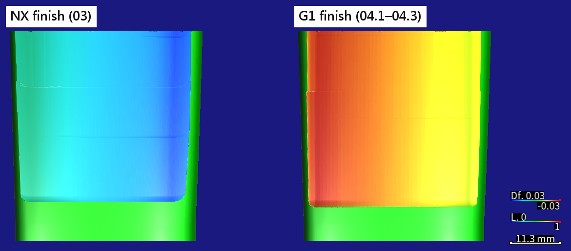
The same machine with its C axis 0.020 mm off, error terms on and the error marked. The picture shows the faces the two finishing programs cut, side by side, in the front view (from −Y onto the finished face). Left, NX is blue all over: material is left and the blade is thicker, with 5–95 % of the face at +0.011 to +0.026 mm. Right, G1 is yellow to red all over: the face is cut too deep and the blade is thinner, with 5–95 % at −0.028 to −0.012 mm. The finishing cutter does not reach the sides and the base, so they are green. Each Diff is taken against its own program's nominal run. Colour scale ±0.03 mm: red = cut too deep, blue = material left, green = 0, both signs weighted alike. 0.0625 mm; a HiNC 3.2.46 development build with error-term branches.
| A HiNC 3.2.46 development build with error-term branches, 0.0625 mm | NX (03) | G1 (04.1–04.3) |
|---|---|---|
| C angle while cutting | 45.1–125.2° | 243.7–298.9° |
| B angle while cutting | −6.56° to −5.00° | +5.24° to +6.58° |
| Cutting steps (the nominal run's steps in contact with the stock) | 1,757 | 1,487 |
| Length of the tip offset | 0.0154–0.0355 mm | 0.0203–0.0340 mm |
| Largest difference of the tip offset from the formula | 2.6 × 10⁻¹³ mm | 1.4 × 10⁻¹³ mm |
| Face deviation, 1st percentile / median / 99th percentile (where the finishing cutter reached) | +0.0101 / +0.0184 / +0.0266 mm | −0.0291 / −0.0215 / −0.0114 mm |
| Blade thickness change (1st–99th percentile) | 0.0101–0.0266 mm thicker | 0.0114–0.0291 mm thinner |
| Mean shift at the paper's measured points (the plan's prediction) | +0.0181 mm (+0.018) | −0.0204 mm (−0.020) |
| Controller aware of the error: tip / cut against the nominal | ≤ 2.4 × 10⁻¹³ mm / ≤ 5 × 10⁻¹⁰ mm | ≤ 1.4 × 10⁻¹³ mm / ≤ 5 × 10⁻¹⁰ mm |
The case
The BCAM blade's own case page tells how the agent built the whole machining from the six Heidenhain programs and the NURBS blade published on Zenodo. It covers roughing, semi-finishing, and the two flank finishes of the blade's front face with conical cutters, all at 0.0625 mm. At the paper's 45 measured points, HiNC's readings came within 0.0019 mm (NX) and 0.0047 mm (G1) of the paper's values on average.
That case used the machine as designed. This page puts one error that is common on five-axis machines on the same machine and answers three questions:
- What does the error look like on the face, and how large is it?
- Which way does it push each of two programs that use opposite B/C solutions?
- What changes when the controller knows the error, that is, when the machine's kinematics are calibrated?
Another error-term study in this series used the same kind of error on the
NIST five-axis cone frustum: a C axis whose centre is off,
under Fanuc G43.4. This case differs in four ways:
- The controller is a Heidenhain running
M128. - Two presets have to be typed in as a touch-off would find them.
- One face is finished by two programs on two B/C solutions.
- The paper published 45 measured points, so the error's effect on the paper's comparison can be estimated.
What the agent was given:
- The accepted project and its programs, from the base case:
- The machine, GenericBC. On the table side, B (about −Y) carries C (about −Z). The two axes meet at the B/C pivot, and the table top lies 100 mm below it. On the spindle side, X, Y and Z carry a vertical spindle.
- The stock and the fixture: a 60 × 50 × 60 mm block of S45C, in place of the paper's AISI 1045, on a riser 86.6 mm tall.
- The finishing tool T22: a tapered ball-end mill with an R3.332 tip ball, a 6° half angle and 28 mm of flutes. It sticks 47 mm out of a shrink-fit holder and has a tool length offset of 127 mm. The base case found the holder at least 5.15 mm from the part.
- The programs.
03.Finishing_NX.h(514 lines) is played as published.04.1–04.3are played from the base case's copies, which change two lines:TOOL CALL 22andCYCL DEF 7.0 DATUM SHIFT. - Two presets:
- Preset 1 = (−30, −25, 46.6) is program zero, at the top corner of the block.
- Preset 2 = (0, 0, −100) is the centre of the C table. The 04.x programs come back from it to the
same program zero with
CYCL DEF 7X−30 Y−25 Z146.6. - The mission's list 6 selects preset 1 with
CYCL DEF 247 Q339=+1and plays 03. Its list 7 selects preset 2 withQ339=+2and plays 04.1–04.3.
- The semi-finished stand-in: a solid made by growing the design surface outward by 0.484 mm.
- HiNC's error terms. An axis or the spindle of the machine chain can be given an error term, a static branch of its own just before the axis's branch.
- The controller is
XyzabcSolver. It turns the NC into machine coordinates and also computes tool centre point control such asM128. It always solves on the nominal chain, as if the marked branch were not there. - While the project's Enable Error Terms switch is on, the simulated machine keeps the branch in place as it moves, cuts and checks collisions.
- So the error is cut into the part, as on a real machine whose controller does not know its own
error. With the mark cleared, the controller takes the branch into its kinematics. Under
M128it then makes up for the error with the linear axes (What a mark changes, Error-Term Branches).
- The controller is
- Touch-off and P0, as the manual states. With a single translation, the error moves the table even at C = 0. On a real machine, the work offset found by touching off takes that shift in. HiNC's P0 measures on the nominal chain, so it does not. To reproduce a real machine's result, type in by hand the work offsets a touch-off would find (Work offsets on a machine with error terms).
- The request. HiNC's product owner asked for error-term showcases built on earlier cases, from product cases and paper cases alike, with the heavy work run on a shared server.
What nothing states:
- What errors this machine really has. The paper names no machine and publishes no measurement of machine errors. The agent chose 0.020 mm as a typical value, and it also chose the sign, +X.
- Which two presets a touch-off would find on a machine with this error. The agent had to derive them from the machine chain (next section).
- How the paper registered its measurement. The paper does not say, and a registration can absorb part of an offset. So the close match between the paper's measurement and the base case's nominal simulation cannot tell whether the authors' machine had this error.
- Whether a 0.0625 mm grid reads deviations of 0.01–0.03 mm. These are only 16–46 % of a cell.
What the agent built
Each value is marked read (from the paper or the base case), derived (computed from what was read) or chosen (the agent's decision).
| Item | Value | Source |
|---|---|---|
| What the error is | The real centre of rotation of the C axis lies off its design position in +X. ISO 230-7 calls this EX0C, the location error of the C axis in the X direction | chosen (the plan) |
| Size | 0.020 mm, in the coordinates of the B anchor (at B = 0, the machine's X direction) | chosen: a size common on five-axis machines without kinematic calibration, not a measurement of any machine; the sign is chosen too |
| Where it sits | Directly upstream of the C axis branch. A new anchor, Cerr, splits the former B→C in two. B→Cerr is named EX0C, carries a Static Translation (0.020, 0, 0) and is marked as an error term. The C axis' Dynamic Rotation (axis (0, 0, −1), pivot (0, 0, 0)) moves whole onto Cerr→C, and Axis C is bound to it again with its values unchanged |
chosen: on 2026-10-06 the product owner ruled that an error goes only upstream of a role branch, meaning an axis or the spindle |
| Machine chain | Table side O→base→frame→B→Cerr→C→w; spindle side base→X→Y→Z→S→t | read back after the build |
| Work offsets | The marked and unmarked runs typed in what a touch-off at B = C = 0 would find: preset 1 = (−29.98, −25, 46.6) and preset 2 = (0.02, 0, −100). The nominal and control runs keep the case's (−30, −25, 46.6) and (0, 0, −100) | derived: EX0C moves the table 0.020 mm in +X even at C = 0, and touching off the block takes that into preset 1. Preset 2 follows the base case's rule: preset 1 plus (30, 25, −146.6). The manual recommends this in Work offsets on a machine with error terms |

The machine cluster (GeneralMechanism) in the Topology column of the Equipment page. A new anchor, Cerr, sits between B and C. EX0C, a Static Translation (0.020, 0, 0) from B to Cerr, is drawn thick and carries the orange Error term badge. The C axis' Dynamic Rotation now runs from Cerr to C and is still bound to Axis C. A HiNC 3.2.46 development build with error-term branches, English interface.
Where the tip goes: the prediction written in the plan. The symbols:
- d stands both for the vector (0.020, 0, 0) mm and for its length.
- RZ and RY are right-handed rotations about +Z and +Y.
- The program's origin is preset 1, the top corner of the block. X runs along the blade's chord, Y through the blade (the finished face faces −Y), and Z up.
The prediction:
The controller assumes the work turns about the design C axis. In fact it turns about an axis d away.
At C = 0, the touched-off preset already holds the extra d the table moves, so the tip lands on the program.
At any other C, the work has moved further than the controller thinks. In program coordinates, which turn with the table, the tip is off by
δ = (I − RZ(C))·d = (d(1 − cos C), −d·sin C, 0).
δ depends on C alone. It does not depend on B, on where the tool is or on the height. Its length is 2d·sin(C/2).
How far the face moves is the part of δ along the face's normal. The finished face faces −Y: its normal is (−0.35, −0.94, 0) near X ≈ 16 and turns to (+0.36, −0.93, 0) near X ≈ 46. The designer agent, the agent that drafted this study, read these normals off the design surface.
- NX cuts near C ≈ 90°, where δ ≈ (+0.020, −0.020, 0). The tool moves towards −Y, off the face and into the air. Material is left, and the blade comes out thicker.
- G1 cuts near C ≈ 270°, where δ ≈ (+0.020, +0.020, 0). The tool moves towards +Y, into the material. The face is cut too deep, and the blade comes out thinner.
The numbers the plan wrote down:
- The medians of five chord segments (X 12–20, 20–28, 28–36, 36–44 and 44–48): NX +0.012, +0.016, +0.020, +0.023 and +0.027 mm; G1 −0.027, −0.024, −0.020, −0.017 and −0.013 mm.
- The mean shift at the paper's 45 points: NX +0.018 mm, G1 −0.020 mm.
- No change with height.
The plan also wrote why this matters. A wrong tool radius moves the faces of both programs the same way, while a wrong C-axis location moves them in opposite ways. That is a clue for telling a tool problem from a machine problem.
Why a location error of the C axis. These are the designer agent's reasons (derived):
From the touch-off pose (B = C = 0), the finishing tilts B by only 5.0–6.6°, but it turns C to 45–125° or 244–299°. The part shows a rotary axis' location error multiplied by 2·sin(angle/2):
- for C, 0.77–1.77 times for NX and 1.02–1.70 times for G1;
- for B, only 0.09–0.12 times, about a tenth.
So “the tool is nearly upright” does not mean the error stays as small as on a three-axis machine.
On the two B/C solutions, the same error has opposite signs in the two programs. Only this case shows that, and it is the most useful point for a reader.
All the cutting runs under
M128, so the unmarked run means something: it stands for a calibrated controller.Only the finishing has to be played: 2,000–2,400 steps a run, all from the same stand-in.
The designer agent compared other candidates too:
- a location error of the C axis in Y would make both blades thinner, so it could not tell the two solutions apart;
- a 0.01° tilt of the C axis shows at most 7.6 µm at the blade's top.
The runs:
| Run | Grid | Error-terms switch | EX0C | X of preset 1 / preset 2 | Purpose |
|---|---|---|---|---|---|
| NX and G1 nominal, trimmed | 0.25 mm | off | marked (not in effect) | −30 / 0 | trimmed: nominal |
| NX and G1 marked, trimmed | 0.25 mm | on | marked | −29.98 / 0.02 | trimmed: the controller unaware; makes the Diff |
| NX and G1 nominal | 0.0625 mm | off | marked (not in effect) | −30 / 0 | exports its cut, the set's ideal geometry |
| NX and G1 control | 0.0625 mm | off | marked (not in effect) | −30 / 0 | makes the Diff, for the noise floor |
| NX and G1 unmarked | 0.0625 mm | on | mark cleared | −29.98 / 0.02 | the controller aware; makes the Diff, exports its cut |
| NX and G1 marked | 0.0625 mm | on | marked | −29.98 / 0.02 | the controller unaware; makes the Diff, exports its cut |
| Holder picture | 0.0625 mm | on | marked | −29.98 / 0.02 | the G1 marked run's stock put back, then the parking program pose-g1-bottom-pass.h played |
Common to every run:
- Physics off. This study is about geometry, so cutting force and deflection are outside it.
- Collision detection on, with no pause on a failure. Each step is one spindle revolution.
- Only the set's own list. Each run enables only its mission list: 6 for NX, 7 for G1. The base case's entries that read its recorded semi-finished stock and that export its finished part are off.
- The Diff (Geometry Validation): detection radius 1 mm, colour scale ±0.03 mm, against the set's own nominal cut.
- Recorded stocks. The control, marked and unmarked runs each recorded their final stock. The pictures put that stock back on the canvas with its Diff.
How the agent managed the work
- Criteria and predictions first. The plan, its predictions and seven criteria were committed at 21:02 on 2026-10-06. The first play started at 21:03.
- Always the stand-in stock. Every run starts from the case's semi-finished stand-in, the design surface grown by 0.484 mm. It does not play the roughing (01) or the semi-finishing (02). The finishing removes all the material on the face, so errors of those first two programs cannot reach it. In the base case, 01 and 02 took 197,265 steps and 1 h 54 min.
- Two run sets. The NX set selects preset 1 with
Q339=+1and plays 03 (list 6). The G1 set selects preset 2 withQ339=+2and plays 04.1–04.3 (list 7). - Trimmed runs first. Four runs at 0.25 mm, nominal and marked for each set, ran one after another on one instance. They checked the build, the per-step δ formula and its sign.
- Eight full runs, one at a time, at 0.0625 mm, the case's acceptance resolution.
- Before each run the private HiNC instance was restarted.
- The eight runs queued on the acceptance lock that the studies on the server share, and ran under one hold of it.
- Other plays shared the server meanwhile, so the wall times were measured under load.
- The nominal cut as the ideal geometry. Each set's nominal run exported its cut, and that cut became the ideal geometry of the set's Diffs. So a Diff shows only what the error changes, not the marks the toolpath itself leaves.
- Mesh distances. The marked and unmarked runs exported their cuts. The agent measured the signed distance of every vertex to the nominal cut. The control runs export no cut.
- Every number from the records. The agent's analysis script computes every number on this page from the run records and keeps the source of each. The analysis can be run again.
- Pictures in both interface languages. They come from the recorded stocks put back on the canvas. The holder picture plays the base case's parking program (dilemma 11).
- Where a person stepped in. HiNC's product owner asked for error-term showcases built on earlier cases. The same day, the owner ruled that an error term goes only upstream of a role branch, meaning an axis or the spindle. That ruling turned the design from a pair of translations into one translation with typed presets (dilemma 1). The error, the predictions and the criteria are the agent's.
The criteria as committed before the first play, summarised from the plan. Two definitions:
- A cutting step is a step of the nominal run in contact with the stock (
IsTouched): 1,757 for NX, 1,487 for G1. - Line numbers count the lines of the program file, not its block numbers. These programs do not number their blocks continuously.
| # | Criterion |
|---|---|
| 1 | Build: the error-term project reopens with no load message; EX0C is a marked Static Translation (0.020, 0, 0) on B→Cerr; Axis C is bound to Cerr→C with the values it had; the roles check is empty; the case's files outside the error-term folder are unchanged |
| 2 | Every run ends Finished; every line of 03 and 04.1–04.3 runs; no collision and no rapid cutting; runs with a Diff add only Diff--TargetNotClosed; the step counts are recorded (about 2,410 for NX and 2,011 for G1 expected) |
| 3 | Marked: on every cutting step, the length of Cl − Cl(nominal) − δ is at most 1 × 10⁻⁶ mm; the signs are as predicted (NX's first feed point at C 49.7, δY < 0; G1 at C ≈ 293, δY > 0) |
| 4 | Unmarked: on every cutting step, the length of Cl − Cl(nominal) is at most 1 × 10⁻⁶ mm |
| 5 | Control: the 99th percentile of the absolute mesh distance is at most 0.005 mm (the noise floor) |
| 6 | The face, the marked cut against the nominal by mesh distance, in the finishing band X 12–48, Z −43 to −3.5: NX at least 99 % positive, G1 at least 99 % negative; the medians of the five chord segments within ±0.004 mm of the prediction; the medians of seven height bands within 0.004 mm of each other |
| 7 | The holder at least 4.8 mm from the part; wall time and VmHWM recorded for every run, and a run stopped above 30 GB |
| Trimmed | From the plan's run section: check how the touch-off presets were derived (δ = 0 on the steps where C ≡ 0) |
The dilemmas
Each dilemma is told as its situation, the risk if it had been missed, how it was noticed, the resolution, and the evidence that the resolution held.
1. A pair of translations, or one translation with both presets typed in
- Situation. The designer agent first proposed a marked translation on each side of C: +d on
B→Cpivotand −d onC→Cback. At the touch-off pose, B = C = 0, the two cancel, so neither preset would need to change. - Risk.
- The product owner ruled the same day that an error term goes only upstream of a role branch, meaning an axis or the spindle. The translation after C breaks that rule.
- With one translation, the table is 0.020 mm off at C = 0 too. If the case's presets were kept, the places cut near C = 0 would also be 0.020 mm off. A real machine that was touched off does not do that.
- This case has two presets. NX runs from preset 1. G1 starts from preset 2, the C-table centre, and
comes back to program zero with
CYCL DEF 7. If only one preset changed, the two programs would no longer share one touch-off.
- How noticed. While the agent rewrote the plan to follow the ruling. The touch-off went into the plan's error section as a line of its own.
- Resolution.
- EX0C goes before C only.
- The marked and unmarked runs type in the presets a touch-off at B = C = 0 would find: preset 1 = (−29.98, −25, 46.6) and preset 2 = (0.02, 0, −100). Preset 2 follows the base case's rule: preset 1 plus (30, 25, −146.6).
- The nominal and control runs keep the case's two values.
- Evidence.
- Every cutting step of both sets meets the formula, within 2.6 × 10⁻¹³ mm.
- The formula has no constant term: δ(0) = 0. So both presets took effect as derived. Otherwise every step would carry a constant difference (dilemma 3).
- The unmarked runs come within 2.4 × 10⁻¹³ mm of the nominal.
- The forward-kinematics expression holds within 1.7 × 10⁻¹³ mm and stands beside these as a consistency check.
2. The real value, or ten times larger
- Situation. The designer agent proposed showing a display value of d = 0.2 mm (×10) in the pictures. The real value would run separately, and would be judged only if the noise floor were at most 0.005 mm.
- Risk.
- At ×10, about 2 % of the points on the lower edge of NX's bottom pass would not reach the stand-in. Their deviation would be cut off at the stand-in's surface (the designer's own calculation), and both pictures and numbers would need converting.
- At the real value, the deviations are only 16–46 % of a 0.0625 mm cell and might drown in the noise.
- How noticed. The cut-off was among the designer's own doubts. A 0.25 mm trial of another case in this series, part 4 of the RPTU benchmark, had found the mesh distance proportional to the size of the error, and readable down to ±2.7 µm.
- Resolution. The plan runs only the real 0.020 mm, at the case's acceptance resolution of 0.0625 mm, with a Diff colour scale of ±0.03 mm.
- Evidence.
- The unmarked cut lies within 5 × 10⁻¹⁰ mm of the nominal.
- 100 % of the control pictures lie within ±0.001 mm.
- The mesh distance and the swept-cutter prediction agree within 0.0004 mm on 99 % of the points.
3. A trimmed check of steps at C = 0, where there are none
- Situation. The plan's run section asked the trimmed runs to check how the touch-off presets were derived. The test was δ = 0 on the steps where C ≡ 0.
- Risk. Taken literally, there is no step to check, so nothing would show directly whether the presets were right. Worse, the −0.020 mm at the tool-change position (C = 0), taken as evidence, would suggest they were wrong.
- How noticed. Listing the steps at C = 0: 2 for NX and 6 for G1, all outside
M128. UnderM128, C is never 0. The steps at C = 0 are:- the tool-change steps of 03 and 04.1;
- the
TOOL CALLsteps of 04.2 and 04.3, which wait where the previous program turned back to B = C = 0 (the tool does not return to the tool-change position); - the steps after each program's
M129that turn back to B = C = 0.
- Resolution. The check was recorded as not possible as written, and the four full marked and
unmarked runs stand in for it. The trimmed runs' per-step series equal the full runs' (bit for bit
for G1; for NX only
IsToucheddiffers).- The test is criterion 3's per-step comparison. On the marked run, Cl(marked) − Cl(nominal) has to equal δ(C) = (I − RZ(C))·d at every step. The formula has no constant term: δ(0) = 0. If the presets had been derived wrong, or had not taken effect, every step would carry a constant difference (−d if they had not taken effect).
- The forward-kinematics expression gives each step's tip as the nominal chain's forward kinematics with the typed presets, plus δ(C). It is only a consistency check. Once the real chain's forward kinematics holds, it reduces to the arithmetic “typed preset = case preset + d”, which does not depend on the machine coordinates. On its own it cannot show whether HiNC used the typed presets.
- Evidence.
- On the two full marked runs, the 2,273 (NX) and 1,843 (G1) steps that follow the formula meet it within 2.6 × 10⁻¹³ and 1.4 × 10⁻¹³ mm, with no constant difference.
- The two unmarked runs' cutting steps come within 2.4 × 10⁻¹³ and 1.4 × 10⁻¹³ mm of the nominal.
- The forward-kinematics expression holds on every step of the four runs within 1.7 × 10⁻¹³ mm.
- At the tool-change position, the two runs' machine coordinates are the same and the tip is off by X −0.020 mm. That is exactly −RZ(0)·d (residual 2.4 × 10⁻¹⁵ and 6.1 × 10⁻¹⁵ mm). The tool-change position is a fixed machine position, and the typed presets cannot move it.
4. Steps that do not follow the formula: the tool change, the first approach and the return of B and C
Situation. On the marked run, the tip offset of 137 NX steps and 168 G1 steps is not δ. The difference reaches 0.0315 mm (NX) and 0.0288 mm (G1) on one axis, and 0.0355 mm (NX) and 0.0339 mm (G1) in length. All these largest differences occur at the last step of the return to B = C = 0, where δ = 0.
Risk. These steps could be read as wrong touch-off presets, or as an error in the model.
How noticed. The agent compared every step, not only the cutting steps, and grouped the steps that miss by program line.
Resolution. Their cause was traced; the details are under the tool tip in the results.
- The tool-change position of 03 and 04.1 is a fixed machine position, and the typed presets cannot
move it. In these two programs, the first
FMAXafterM128is interpolated from there in machine coordinates, and the offset changes along it to δ. - In 04.2 and 04.3 the tool does not return to the tool-change position.
TOOL CALLand the B/C pre-rotation wait at the previous program's end point, and the firstFMAXis interpolated from there. That is again a transition. - The return of B and C after
M129is a transition too.
Criterion 3 judges only the cutting steps, and it holds as written; these steps are listed apart. It follows that on a real machine with the same error, this approach would be off by the same amounts, all of it in the air.
- The tool-change position of 03 and 04.1 is a fixed machine position, and the typed presets cannot
move it. In these two programs, the first
Evidence. None of the 137 and 168 steps touches the stock. Forward kinematics from each run's own machine coordinates matches every step within 1.7 × 10⁻¹³ mm.
5. Which run to compare the machine coordinates with
Situation. The plan predicted “unmarked: MC.X/Y/Z move further by (d(1 − cos C)·cos B, d·sin C, d(1 − cos C)·sin B), at most about 40 µm”. It did not name the run this is compared with. The documentation also says that each step's machine coordinates are the same with the error-term switch on and off.
Risk. Two statements would contradict the measurement: “the unmarked run moves at most 40 µm further than the nominal”, and “the marked run's machine coordinates equal the nominal run's”.
How noticed. While comparing the three runs' machine coordinates step by step. The nominal run uses the case's presets (X −30 and 0); the marked and unmarked runs use the touch-off presets (X −29.98 and 0.02).
Resolution. The page states what was measured, and each comparison gets its own formula (see the table under “The controller that knows the error”):
- The plan's formula is in fact unmarked minus marked.
- Unmarked minus nominal is a constant 0.020 mm, RY(−B)·d, at every step that follows the formula.
- Marked minus nominal is 0.020 mm at those steps too: the touch-off preset turned through
M128.
“The switch does not change the machine coordinates” holds only when the work offsets are the same.
Evidence. The three comparisons leave residuals of 1.3–2.4 × 10⁻¹³ mm. B and C are the same in all three runs, bit for bit.
6. “At least 99 % positive” for NX: over the whole box, or where the finishing cutter reached
Situation. Criterion 6 asks for at least 99 % of the NX face to be positive within “the finishing band X 12–48, Z −43..−3.5”. Over the whole box, 99.49 % of the 446,701 face vertices are above 0, but only 98.99 % are above 1 × 10⁻⁶ mm.
Risk.
- Taken literally (d > 0) over the whole box, 99.49 % passes. But about 2,230 of those points are only noise of ±5 × 10⁻¹⁰ mm between the two runs on the same stand-in surface, and they happen to be positive. The 4,510 noise points listed below split about half positive, half negative.
- With a 1 × 10⁻⁶ mm threshold that excludes the noise, the whole box reaches only 98.99 % and fails. Almost all of the shortfall lies on the strip of stand-in that NX's bottom pass did not reach.
How noticed. By locating the 4,524 points that are not positive:
- 4,510 lie at the bottom of the box, Z −43.0 to −41.8, at least 0.45 mm from the design surface. This is stand-in surface that NX's bottom pass never reached. The two runs have the same surface there, within ±1 × 10⁻⁶ mm.
- 14 lie at the pass boundary near Z −16.0 (X 12.4–26.7), at −0.00035 to −0.000003 mm.
Resolution. The share is counted only where the finishing cutter reached: 99.997 % of the 440,576 vertices are above 1 × 10⁻⁶ mm. The designer's “finishing band” for the prediction also counted only points the finishing cutter reached (21,789 of 22,010 face grid points). Both use the same kind of scope, decided by different tests:
- the design keeps the grid points the nominal cutter envelope reaches, leaving out 1.0 %;
- the measurement keeps marked-run vertices less than 0.45 mm from the design surface, leaving out 1.4 %.
The verdict says which scope it uses, and both whole-box numbers are listed.
Evidence. The analysis record of the NX marked run's face band, which counts the vertices of wrong sign or zero.
7. NX's last chord segment 0.0010 mm below the prediction
Situation. On the last chord segment (X 44–48), NX measured +0.0260 mm where the plan wrote +0.027 mm. The designer's first-order formula gives +0.0267 mm.
Risk. The miss is within the ±0.004 mm tolerance. But it is the only one of the five segments that misses by 0.001 mm, and it could be read as HiNC cutting too little or too much.
How noticed. The agent set the measurement beside both predictions, segment by segment: the designer's first-order formula and the swept cutter.
Resolution.
- The first-order formula projects δ onto the design surface's normal. The mesh distance is measured along the nominal cut's normal.
- At the NX tail, the nominal cut is tilted about 1.2° from the design surface (median; 95th percentile 8.6°).
- Projected onto the cut's own normal, or with the cone swept along the measured tip path, the prediction is +0.0259 mm.
The measured value is reported as it was measured. The tilt was approximated by the cone's surface normal at the contact point, and it is used only to explain this 0.001 mm.
Evidence. The swept-cutter segments in the analysis record.
8. Extremes of the mesh distance that are edge artefacts
- Situation. Over the whole part, the largest mesh distances are +0.25 mm for G1 and +0.058 mm for NX, and the smallest is −0.055 mm for G1. All lie far outside the predicted ±0.03 mm.
- Risk. Quoted as the largest and smallest values, they would suggest that the blade's top or leading edge was damaged.
- How noticed. The agent listed the vertices more than 0.04 mm away: 25 for NX and 24 for G1.
- Resolution.
- All of them lie outside the finishing band. NX's 25 and 15 of G1's sit on the top edge of the face (Z −3.0, where the stand-in's top meets the face). G1's values there are whole multiples of the 0.0625 mm cell: +0.0625, +0.125 and +0.25. G1's other 9 sit on a pass boundary at the leading edge, at X < 12 (Z −16.9).
- Every statistic uses only the points inside the finishing band. For the whole part, only the 1st, 5th, 95th and 99th percentiles are quoted, never the extremes.
- The cause was not found. Perhaps the exported mesh steps by one cell where the face meets the flat top. Or the distance search, which looks only at the 12 nearest triangles, goes wrong near sharp edges.
- Evidence. The list of vertices more than 0.04 mm away in the analysis record.
9. A control run with no mesh of its own
- Situation. Criterion 5 judges the control run's noise floor by the 99th percentile of its mesh distance. But this batch's tools export no cut on a control run.
- Risk. Criterion 5 cannot be measured as written.
- How noticed. While the analysis was being written: the control runs had no mesh to measure.
- Resolution. The NIST cone frustum's error-term study met the same gap. As there, three pieces of
evidence judge the noise floor: the per-step series,
Diff--Statsand the Diff pictures read by hue. The unmarked run's mesh adds supporting evidence, since itsDiff--Statsequal the control run's. - Evidence. Criterion 5 in the results.
10. The paper's 45 points can only be derived
- Situation. The paper's points were measured after finishing a real semi-finished stock. Every run here starts from the stand-in, with physics off, to save the roughing and semi-finishing (197,265 steps, 1 h 54 min).
- Risk. “Base reading plus shift” could be written up as a measurement or a play. Or the two might not add at all.
- How noticed. The design planned it that way. The analysis confirmed that the points are the base case's: every point's height agrees with the base report.
- Resolution. The shift at a point is the median of the marked cut's face vertices within 0.1 mm of
it. The shift is added to the base case's accepted reading, and the result is marked “derived”
throughout. The two can be added because:
- finishing removes all the material at these points, so the starting stock leaves no trace;
- the base case's trimmed run (on the stand-in) and its full acceptance differ by at most 0.0014 mm at the 45 points.
- Evidence.
- The mean shifts, NX +0.0181 and G1 −0.0204 mm, are within 0.00003 mm of the design table's means. Point by point, they are within 0.00047 mm (NX) and 0.00085 mm (G1).
- The design table was committed after the plays. The plan, committed before them, gives the means +0.018 and −0.020 mm.
- The cone swept at the same points gives matching shifts too.
11. The holder picture's parking program has to use that run's typed presets
- Situation. The holder picture puts the G1 marked run's recorded stock back on the canvas with its
Diff. It then plays the base case's parking program,
pose-g1-bottom-pass.h(the G1 copy of 04.3 cut after block 46), which stops the tool in the middle of the bottom pass. - Risk. Played with the nominal presets (X −30 and 0), the tool would stand 0.020 mm off the part already cut, and it could cut the recorded stock again. The Diff in the picture would then no longer be what the marked run cut.
- How noticed. While the pictures were being prepared.
- Resolution. Before the agent's tool puts the stock back, it types in that run's presets (preset 1 X −29.98, preset 2 X 0.02). Afterwards it restores them.
- Evidence. That play ran 381 steps in 205.3 s, ended
Finishedand reportedPlay-Touch--None: it touched no material at all.
Results and benefits
Measured on a HiNC 3.2.46 development build with error-term branches, at 0.0625 mm with physics off.
| # | Verdict | Measured |
|---|---|---|
| 1 | met where measured; one item not recorded | EX0C is on B→Cerr, a marked Static Translation (0.02, 0, 0). C is the Dynamic Rotation on Cerr→C (axis (0, 0, −1), pivot (0, 0, 0)), bound to Axis C, with the same values before and after the move. The roles check was empty before and after the build, and in each of the 12 plays. The project reloaded after Save As with no message, and the base case also loads with none. Not recorded: whether the case's files outside the error-term folder stayed unchanged. The build ran on a working copy on the server, and the state of its files was not kept with the results |
| 2 | met | All 12 runs (8 at 0.0625 mm, 4 at 0.25 mm) ended Finished. NX had 2,410 steps a run and G1 2,011, as in the base case. In every program, every L block with an axis word has a step, except the opening L B+0.0 C+0.0 FMAX: the axes are already there, so the move has length 0. The last motion lines (line 512 of 03, line 72 of 04.1 and 04.2, line 77 of 04.3) have steps too. At warning level and above, the nc, step and ncManip message sinks were empty; shell held only one Diff--TargetNotClosed in each of the 8 runs with a Diff. No Collision--Detected and no rapid cut. The records keep only warnings and above, so “every line ran” is inferred from every motion line having a step |
| 3 | met | The two runs have the same steps and are lined up by step index. NX's 1,757 cutting steps are within 2.6 × 10⁻¹³ mm, G1's 1,487 within 1.4 × 10⁻¹³ mm. NX's first cutting step is line 22 of 03, at C 49.719°: δ = (+0.00707, −0.01526, 0). G1's first is line 20 of 04.1, at C 292.935°: δ = (+0.01221, +0.01842, 0). Both are as predicted, (+0.0071, −0.0153, 0) and (+0.0122, +0.0184, 0), and C does not change from the first feed block to that step. The 0.25 mm trimmed runs give the same 2.6 × 10⁻¹³ and 1.4 × 10⁻¹³ mm. Of the non-cutting steps, 137 (NX) and 168 (G1) do not follow the formula, and none of them touches the stock (dilemma 4) |
| 4 | met | NX within 2.4 × 10⁻¹³ mm, G1 within 1.4 × 10⁻¹³ mm. The non-cutting tool changes, approaches and retracts behave as under criterion 3 |
| 5 | met, judged on the pictures, the series and Diff--Stats |
The control runs exported no cut (dilemma 9). So, as in the NIST cone frustum's error-term study, three pieces of evidence judge it. (1) The per-step series equals the nominal run's bit for bit, in both sets. (2) The eight numbers of Diff--Stats equal the unmarked run's exactly. (3) The front and isometric Diff pictures, read by hue, have 100 % of their pixels within ±0.001 mm (extremes −0.00019 to +0.00023 mm), and they equal the unmarked run's pictures byte for byte. In addition, every vertex of the unmarked run's exported cut lies within 5.0 × 10⁻¹⁰ mm of the nominal (99th percentile 4.8 × 10⁻¹⁰ mm) |
| 6 | met (NX's 99 % counted where the finishing cutter reached; dilemma 6) | NX: of the 440,576 vertices the finishing cutter reached, 99.997 % are above 1 × 10⁻⁶ mm. Taken literally over the whole box (446,701 vertices), 99.49 % are above 0 and only 98.99 % above 1 × 10⁻⁶ mm; the rest lie almost all on a strip of stand-in surface at the bottom of the box that NX's bottom pass did not reach. G1: all 445,950 vertices are negative. Chord segment medians: NX +0.0123, +0.0161, +0.0195, +0.0227 and +0.0260 mm; G1 −0.0271, −0.0239, −0.0204, −0.0168 and −0.0129 mm; at most 0.0010 and 0.0004 mm from the prediction. Spread of the seven height-band medians: NX 0.0004 mm (whole box 0.0009 mm), G1 0.0006 mm |
| 7 | met | The holder clearance is derived: the base case's 5.15 mm less the tool's largest movement relative to the part, 0.0355 mm, leaves at least 5.11 mm. None of the 12 runs, all with collision detection on, reported Collision--Detected. The eight 0.0625 mm runs took 55.1–285.5 s. The highest VmHWM was 5.64 GiB (6.05 GB, NX marked), far below 30 GB. The four 0.25 mm runs on one instance peaked cumulatively at 6.10 GiB (6.55 GB) |
| Trimmed | not possible as written; the full runs' per-step comparison stands in | Under M128 no step is at C = 0: the cutting runs at C 45–125° and 244–299°. The steps at C = 0 (2 for NX, 6 for G1) all lie outside M128 (dilemma 3). The full marked and unmarked runs stand in, since the trimmed series equal the full ones (G1 bit for bit, NX differing only in IsTouched). The evidence is the per-step comparison of criteria 3 and 4. Cl(marked) − Cl(nominal) equals δ(C) = (I − RZ(C))·d at every step within 2.6 × 10⁻¹³ mm, and the formula has no constant term, δ(0) = 0. The unmarked run is within 2.4 × 10⁻¹³ mm of the nominal. Presets derived wrong, or not in effect, would add a constant difference to every step. The forward-kinematics expression (nominal chain + typed presets + δ(C), residual within 1.7 × 10⁻¹³ mm) stands beside this as a consistency check (dilemma 3) |
The tool tip: every cutting step on the formula
Here the tool tip means each step's CL: the actual tip position in program coordinates. The two runs of a set have the same number of steps (NX 2,410, G1 2,011), so they can be lined up step by step and subtracted. The residuals are of the order of 10⁻¹³ mm, which shows that every step is paired correctly.
| Comparison | Over | NX | G1 |
|---|---|---|---|
| Marked minus nominal, minus δ | cutting steps | 2.6 × 10⁻¹³ mm (1,757 steps) | 1.4 × 10⁻¹³ mm (1,487 steps) |
| The same | every step that follows the formula | 2,273 of 2,410 steps, 2.6 × 10⁻¹³ mm | 1,843 of 2,011 steps, 1.4 × 10⁻¹³ mm |
| Marked minus nominal: length of the offset | cutting steps | 0.0154–0.0355 mm | 0.0203–0.0340 mm |
| Marked minus nominal: largest X / Y / Z, absolute | cutting steps | 0.0315 / 0.0200 / 2.6 × 10⁻¹³ mm | 0.0289 / 0.0200 / 1.4 × 10⁻¹³ mm |
| Tool axis, marked minus nominal | every step | 4.4 × 10⁻¹⁶ | 4.4 × 10⁻¹⁶ |
| Unmarked minus nominal | cutting steps | 2.4 × 10⁻¹³ mm | 1.4 × 10⁻¹³ mm |
| Control minus nominal | every step | 0: the two series are identical, bit for bit | 0 |
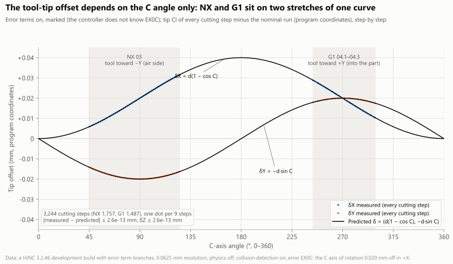
Error terms on, marked: the tip offset of every cutting step against the C angle. The offset is the step's CL minus the nominal run's, in program coordinates. The dots are measured; one dot per 9 steps is drawn. The black lines are the formula (d(1 − cos C), −d·sin C) with d = 0.020 mm. NX (C 45–125°) has δY negative and G1 (C 244–299°) positive: the 3,244 steps of NX and G1 are two stretches of one curve, within 2.6 × 10⁻¹³ mm of the formula. The vertical axis is symmetric. A HiNC 3.2.46 development build with error-term branches, 0.0625 mm.
The signs of the two sets.
- NX's first cutting step is line 22 of 03, at C 49.719° and B −5.997°. It measured δ = (+0.00707, −0.01526, 0).
- G1's first is line 20 of 04.1, at C 292.935° and B +6.044°. It measured δ = (+0.01221, +0.01842, 0).
- Both agree with the prediction to every digit given.
G1's C angle. The G1 runs report the machine's C as −116.3° to −61.1°:
M126takes the short way round. These are the same angles as 243.7–298.9°. The formula uses only cos and sin, so it is not affected.The 137 and 168 steps that miss the formula (dilemma 4) are all non-cutting. Not one touches the stock. They fall into four groups:
- At the tool-change position: the
TOOL CALLon line 5 of 03 and 04.1, and the B/C pre-rotation there, on line 8 (03) and line 13 (04.1). Both runs have the same machine coordinates here, and the typed presets cannot move them. So relative to the part the tip is off by −RZ(C)·d, which at C = 0 is X −0.020 mm, the error itself. This group has 9 NX steps and 11 G1 steps, with residuals of 2.4 × 10⁻¹⁵ and 6.1 × 10⁻¹⁵ mm against that expression. - Where the previous program ended: the
TOOL CALLon line 5 of 04.2 and line 10 of 04.3 (one step each), and the B/C pre-rotation in place that follows, on line 13 (04.2, 10 steps) and line 18 (04.3, 9 steps). The tool does not go back to the tool-change position. It waits where the previous program turned back to B = C = 0 afterM129. There the two runs' machine coordinates already differ, so the offset is not −0.020 mm. On line 5 of 04.2 it is (−0.0277, +0.0184, −0.0008) mm. - The first
FMAXafterM128: line 10 of 03, 109 steps; lines 15, 15 and 20 of 04.1, 04.2 and 04.3, with 66, 9 and 9 steps.- In 03 and 04.1, this move is interpolated in machine coordinates from the tool-change position. The offset changes along it from −RZ(C)·d to δ.
- In 04.2 and 04.3, the move starts from the previous program's end point. The offset changes from its value there to δ.
- The return to B = C = 0 after
M129: line 512 of 03, 19 steps; 17, 17 and 18 steps in 04.1, 04.2 and 04.3. This is likewise a transition between the two.
- At the tool-change position: the
A consistency check by forward kinematics, from each run's own machine coordinates:
- On every step of the eight full runs, the tip equals the position measured from where program zero really is, through the real machine chain (with EX0C while the switch is on), within 1.7 × 10⁻¹³ mm.
- On every step of the four marked and unmarked runs, the tip also equals the nominal chain's position with the typed presets, plus δ(C), within 1.7 × 10⁻¹³ mm.
So at every step, these 137 and 168 included, the machine with EX0C moves the tip by δ from the nominal chain's position. The two expressions differ only by a constant: typed preset − case preset − d, which is 0 and does not depend on the machine coordinates. So the second expression alone cannot prove that the typed presets took effect. That proof rests on criterion 3's per-step comparison having no constant term (dilemma 3).
The trimmed runs at 0.25 mm and the full runs at 0.0625 mm have the same per-step series (compared by the MD5 of the decompressed series):
- G1 is identical: nominal = trimmed nominal = control, and marked = trimmed marked.
- NX differs only in
IsTouched, the flag for whether a step touches the stock: on 11 steps of the nominal run and 10 of the marked run. That flag depends on the grid. The tip and the machine coordinates are the same.
Steps in contact. The NX marked run has 6 fewer steps in contact than its nominal run: 7 steps touch only in the nominal and 1 only in the marked. The G1 marked run has 1 more. This fits the direction of the error: NX's tool moves into the air, G1's into the material.
The face: NX leaves material, G1 cuts too deep
How it was measured:
- For each marked run's exported cut (NX 1,418,426 vertices, G1 1,416,898), the agent measured each vertex's signed distance to the same set's nominal cut. Positive = material left (blue in the Diff); negative = cut too deep (red).
- The face is the vertices within 1 mm of the base case's registered grid of the design face (480 × 210 points), inside the box X 12–48, Z −43 to −3.5.
- Of those, the vertices at least 0.45 mm from the design surface count as stand-in (the stand-in lies at 0.484 mm). The finishing cutter did not reach them, or wiped less than 0.034 mm off. NX has 6,125 such vertices, all at the bottom of the box, Z −43 to −41.6; G1 has none. The rest is “where the finishing cutter reached”.
| NX (03) | G1 (04.1–04.3) | The design's prediction (NX; G1) | |
|---|---|---|---|
| Face vertices in the box | 446,701 | 445,950 | |
| Vertices the finishing cutter reached | 440,576 | 445,950 | |
| Sign (where the finishing cutter reached) | 99.997 % above +1 × 10⁻⁶ mm | 100 % below −1 × 10⁻⁶ mm | 100 % positive; 100 % negative |
| 1st percentile / median / 99th percentile | +0.0101 / +0.0184 / +0.0266 mm | −0.0291 / −0.0215 / −0.0114 mm | +0.010 / +0.0175 / +0.028; −0.029 / −0.0225 / −0.012 |
| Smallest to largest | −0.00035 to +0.0343 mm | −0.0298 to −0.0052 mm | |
| Spread of the seven height-band medians | 0.0004 mm | 0.0006 mm | ≤ 0.001; ≤ 0.0007 |
The medians differ from the design's prediction by about 0.001 mm because the two sample the face differently. The design's statistics use the points of the face grid, which thin out towards +X. The measurement uses the mesh vertices, spread more evenly along the chord. Swept again along the measured tip path, on the design's own face points, the cone gives medians of exactly +0.0175 and −0.0225 mm. The median difference between the measurement and that sweep is at most 0.000004 mm.
The medians of the five chord segments. “C” is the median C angle of the steps that finished the points.
| Chord segment X (mm) | C: NX / G1 | NX measured | NX predicted (plan) | NX swept | G1 measured | G1 predicted (plan) | G1 swept |
|---|---|---|---|---|---|---|---|
| 12–20 | 55.6° / 250.0° | +0.0123 | +0.012 | +0.0124 | −0.0271 | −0.027 | −0.0270 |
| 20–28 | 74.1° / 258.4° | +0.0161 | +0.016 | +0.0161 | −0.0239 | −0.024 | −0.0239 |
| 28–36 | 92.5° / 268.5° | +0.0195 | +0.020 | +0.0195 | −0.0204 | −0.020 | −0.0204 |
| 36–44 | 109.5° / 278.0° | +0.0227 | +0.023 | +0.0228 | −0.0168 | −0.017 | −0.0168 |
| 44–48 | 124.3° / 291.5° | +0.0260 | +0.027 | +0.0259 | −0.0129 | −0.013 | −0.0129 |
In mm. The largest differences from the plan are 0.0010 mm for NX (the last segment, dilemma 7) and 0.0004 mm for G1. The plan's tolerance is ±0.004 mm.
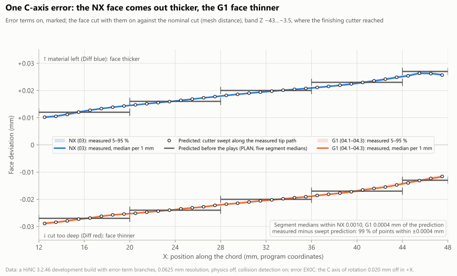
Face deviation along the chord: the face the marked run cut, against its own nominal cut (mesh distance, Z −43 to −3.5, where the finishing cutter reached). Blue is NX's median per 1 mm, with its 5–95 % band, all above 0. Orange is G1, all below 0. The black circles are the cone swept along the measured tip path; the grey bars are the five segment medians predicted before the plays. Positive = material left (Diff blue), negative = cut too deep (Diff red). The vertical axis is symmetric. A HiNC 3.2.46 development build with error-term branches, 0.0625 mm.
- Why NX leaves more towards +X. Along the chord the face normal turns by about 40°, and the C of the finishing steps turns from 56° to 124°. Together they raise δ's component along the normal from +0.012 to +0.026 mm. For G1, C turns from 250° to 291°, and the deviation rises from −0.027 to −0.013 mm.
- No change with height. Over seven bands from Z −43 to −3.5, NX's medians lie between +0.0182 and +0.0186 mm, and G1's between −0.0212 and −0.0218 mm. The whole tool is shifted, so the deviation does not depend on the pass or the height.
- An independent geometric check. This check does not go through HiNC's cutting simulation:
- The T22 cone (tip ball R3.332, half angle 6°, 28 mm of flutes) was placed at every step in contact of the nominal and marked runs, with the tip and the axis taken from the per-step series.
- For each face point, the nearest cone surface gives the finished face. Two finished faces result, and their difference is the prediction.
- The prediction and HiNC's mesh distance agree within ±0.0004 mm on 99 % of the points (NX 21,640 points, G1 22,010).
- Blade thickness. The finishing programs do not touch the back of the blade. Further than 1 mm from the design surface lie the back, the two rounded ends, the top and the bottom (NX 720,453 vertices, G1 720,459), and none of these vertices moved more than 0.0005 mm. So the change in blade thickness equals the front-face deviation: NX 0.0101–0.0266 mm thicker, G1 0.0114–0.0291 mm thinner (1st to 99th percentile).
- The extremes of the whole part are not deviations (dilemma 8). G1's largest, +0.25 mm, and NX's largest, +0.058 mm, sit on the top edge of the blade (Z −3.0). G1 also has 9 points of −0.040 to −0.055 mm on a pass boundary of the leading edge, at X < 12. All these lie outside the finishing band. The whole part's percentiles are not affected: NX's 95th and 99th percentiles are +0.0249 and +0.0263 mm; G1's 1st and 5th are −0.0287 and −0.0271 mm.
Each of the four pictures below alternates in place, at one camera, between error terms on (marked) and off (control).
- The pictures come from putting each recorded stock back on the canvas with its Diff. Nothing was played again.
- The canvas shows no interface text, so the English and Chinese canvas captures are identical byte for byte. Only the labels follow the language.
- The front view reuses the base case's camera on the face, from −Y onto the finished face. The isometric view is HiNC's default isometric view, zoomed.
NX (03), the Diff in the front view, alternating in place between error terms on (marked) and off (control). With error terms on, the face is blue all over: +0.011 to +0.026 mm, material left, more towards +X. With error terms off, it is all green. The finishing cutter does not reach the sides and the base, so they are green in both frames. Diff colour scale ±0.03 mm (red = cut too deep, blue = material left, green = 0, both signs weighted alike); 0.0625 mm; a HiNC 3.2.46 development build with error-term branches.
NX (03), the Diff in the isometric view, alternating in place between error terms on (marked) and off (control). The finishing cutter does not reach the top, the sides and the base, so they are green in both frames. Scale, grid and build as above.
G1 (04.1–04.3), the Diff in the front view, alternating in place between error terms on (marked) and off (control). With error terms on, the face is yellow to red all over: −0.028 to −0.012 mm, cut too deep, deeper towards −X. With error terms off, it is all green. Scale, grid and build as above.
G1 (04.1–04.3), the Diff in the isometric view, alternating in place between error terms on (marked) and off (control). Scale, grid and build as above.
Reading the Diff pictures by hue. On the Df colour bar, blue (hue 240°) is +0.03 mm, green (120°) is 0, and red (0°) is −0.03 mm. The hue in the captures is linear in the position on the bar (largest deviation 0.1°), and 1° of hue equals 0.00025 mm. On the marked runs' front pictures, the pixels that deviate by more than 0.002 mm read:
- NX: median +0.0178 mm, 5–95 % at +0.0104 to +0.0251 mm;
- G1: median −0.0203 mm, 5–95 % at −0.0282 to −0.0147 mm.
This agrees with the mesh distance.
The paper's 45 points, derived
The paper's deviation map labels 20 points on the NX half and 25 on the G1 half; the base case read their values. The derivation:
- At each point, the shift this error causes is the median of the marked cut's face vertices within 0.1 mm.
- The shift is added to the base case's accepted HiNC reading.
The base readings come from the real semi-finished stock with physics on. The shifts come from the stand-in with physics off. Finishing removes all the material at these points, so the two can be added. The result is a derivation, not a play (dilemma 10).
| NX (20 points) | G1 (25 points) | |
|---|---|---|
| Mean shift: measured | +0.0181 mm | −0.0204 mm |
| Mean shift: the design's prediction | +0.018 mm | −0.020 mm |
| Largest difference from the design's prediction, point by point | 0.00047 mm | 0.00085 mm |
| Range of the shift | +0.0114 to +0.0253 mm | −0.0284 to −0.0123 mm |
| Range of the base case's HiNC readings | −0.001 to +0.141 mm | −0.017 to +0.024 mm |
| Range derived (base + shift) | +0.0186 to +0.161 mm | −0.0333 to +0.0117 mm (mean −0.0158) |
| Points outside ±0.01 mm: paper / base case / derived | 14 / 14 / 20 | 0 / 9 / 20 |
| Mean of rows 4–5: base → derived | +0.1126 → +0.1307 mm | −0.003 → −0.0234 mm |
- The NX–G1 gap grows by about a third. The gap between the NX and G1 means of rows 4–5 is the base case's criterion on the bottom two rows. It grows from 0.1156 mm to 0.1541 mm, about 33 % more. From the paper's labelled values it is 0.1125 mm.
- Which predictions came before the plays. The designer agent wrote 0.116 → 0.154 mm and 9 → 20 G1 points. These numbers and its per-point table are in its design record. It was written before the plan, but committed at 21:54, after the twelve plays (21:03–21:48). The plan, committed before the plays, wrote the means +0.018 and −0.020 mm; the measured means are +0.0181 and −0.0204 mm.
- G1 would leave the paper's band. The paper measured all 25 G1 points within ±0.01 mm. On this machine, with its C axis 0.020 mm off and uncalibrated, 20 would fall outside, by this derivation.
- The paper's own comparison says nothing about this error. The paper's measurement and the base case's nominal simulation differ on average by only 0.0019 mm (NX) and 0.0047 mm (G1). But the paper does not say how it registered its measurement, so this cannot settle whether the authors' machine had this error.
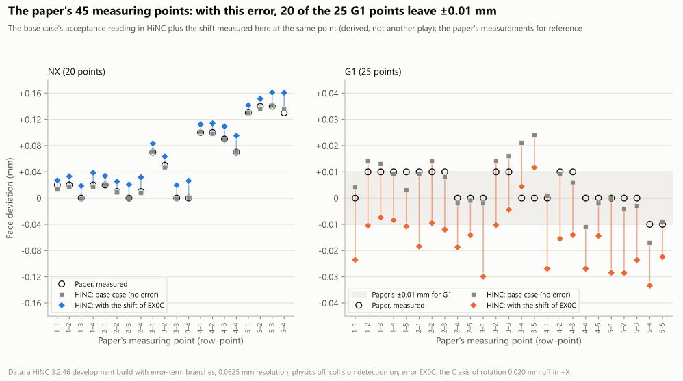
The paper's 45 measured points, derived. Grey squares are the base case's accepted HiNC readings. Diamonds add the shift measured here at the same point. Open circles are the paper's measurements. NX keeps 0.011 to 0.025 mm more at every point. G1 is cut 0.012 to 0.028 mm deeper, and its points outside ±0.01 mm go from 9 to 20 of 25. The vertical axes are symmetric. A HiNC 3.2.46 development build with error-term branches, 0.0625 mm.
The 45 points, in mm
| Program | Row–point | Height Z | Paper | Base case, HiNC | Shift measured here | Shift the design predicted | Derived: base + shift |
|---|---|---|---|---|---|---|---|
| NX | 1–1 | −7.6 | +0.02 | +0.014 | +0.01295 | +0.013 | +0.0270 |
| NX | 1–2 | −9.2 | +0.02 | +0.017 | +0.01607 | +0.016 | +0.0331 |
| NX | 1–3 | −8.5 | −0.00 | −0.001 | +0.01957 | +0.020 | +0.0186 |
| NX | 1–4 | −8.5 | +0.02 | +0.017 | +0.02185 | +0.022 | +0.0388 |
| NX | 2–1 | −18.9 | +0.02 | +0.021 | +0.01279 | +0.013 | +0.0338 |
| NX | 2–2 | −17.5 | +0.01 | +0.009 | +0.01637 | +0.016 | +0.0254 |
| NX | 2–3 | −17.9 | −0.00 | −0.000 | +0.02076 | +0.021 | +0.0208 |
| NX | 2–4 | −18.7 | +0.01 | +0.008 | +0.02376 | +0.024 | +0.0318 |
| NX | 3–1 | −26.2 | +0.07 | +0.071 | +0.01216 | +0.012 | +0.0832 |
| NX | 3–2 | −25.5 | +0.05 | +0.047 | +0.01636 | +0.016 | +0.0634 |
| NX | 3–3 | −25.9 | −0.00 | −0.001 | +0.02056 | +0.021 | +0.0196 |
| NX | 3–4 | −26.3 | +0.00 | +0.001 | +0.02530 | +0.025 | +0.0263 |
| NX | 4–1 | −32.0 | +0.10 | +0.101 | +0.01140 | +0.011 | +0.1124 |
| NX | 4–2 | −32.1 | +0.10 | +0.098 | +0.01587 | +0.016 | +0.1139 |
| NX | 4–3 | −32.5 | +0.09 | +0.089 | +0.02031 | +0.020 | +0.1093 |
| NX | 4–4 | −32.8 | +0.07 | +0.070 | +0.02520 | +0.025 | +0.0952 |
| NX | 5–1 | −41.0 | +0.13 | +0.130 | +0.01159 | +0.012 | +0.1416 |
| NX | 5–2 | −40.4 | +0.14 | +0.136 | +0.01547 | +0.015 | +0.1515 |
| NX | 5–3 | −40.8 | +0.14 | +0.141 | +0.01998 | +0.020 | +0.1610 |
| NX | 5–4 | −40.8 | +0.13 | +0.136 | +0.02461 | +0.025 | +0.1606 |
| G1 | 1–1 | −7.2 | −0.00 | +0.004 | −0.02748 | −0.027 | −0.0235 |
| G1 | 1–2 | −7.6 | +0.01 | +0.014 | −0.02448 | −0.025 | −0.0105 |
| G1 | 1–3 | −8.1 | +0.01 | +0.013 | −0.02035 | −0.020 | −0.0074 |
| G1 | 1–4 | −7.7 | +0.01 | +0.009 | −0.01737 | −0.017 | −0.0084 |
| G1 | 1–5 | −8.1 | +0.01 | +0.003 | −0.01385 | −0.013 | −0.0108 |
| G1 | 2–1 | −14.3 | +0.01 | +0.009 | −0.02743 | −0.027 | −0.0184 |
| G1 | 2–2 | −14.4 | +0.01 | +0.014 | −0.02346 | −0.024 | −0.0095 |
| G1 | 2–3 | −15.2 | +0.01 | +0.008 | −0.02003 | −0.020 | −0.0120 |
| G1 | 2–4 | −14.4 | +0.00 | −0.002 | −0.01671 | −0.017 | −0.0187 |
| G1 | 2–5 | −14.5 | +0.00 | −0.001 | −0.01312 | −0.013 | −0.0141 |
| G1 | 3–1 | −23.7 | −0.00 | −0.002 | −0.02786 | −0.028 | −0.0299 |
| G1 | 3–2 | −23.4 | +0.01 | +0.014 | −0.02434 | −0.024 | −0.0103 |
| G1 | 3–3 | −24.1 | +0.01 | +0.016 | −0.02043 | −0.020 | −0.0044 |
| G1 | 3–4 | −23.8 | +0.00 | +0.021 | −0.01662 | −0.017 | +0.0044 |
| G1 | 3–5 | −23.8 | +0.00 | +0.024 | −0.01230 | −0.013 | +0.0117 |
| G1 | 4–1 | −32.0 | +0.00 | +0.001 | −0.02790 | −0.028 | −0.0269 |
| G1 | 4–2 | −32.4 | +0.01 | +0.009 | −0.02451 | −0.024 | −0.0155 |
| G1 | 4–3 | −32.1 | +0.01 | +0.006 | −0.01995 | −0.020 | −0.0140 |
| G1 | 4–4 | −31.8 | −0.00 | −0.011 | −0.01593 | −0.016 | −0.0269 |
| G1 | 4–5 | −32.2 | −0.00 | −0.002 | −0.01239 | −0.013 | −0.0144 |
| G1 | 5–1 | −40.0 | +0.00 | +0.000 | −0.02841 | −0.029 | −0.0284 |
| G1 | 5–2 | −40.4 | −0.00 | −0.004 | −0.02449 | −0.025 | −0.0285 |
| G1 | 5–3 | −40.8 | +0.00 | −0.003 | −0.02056 | −0.020 | −0.0236 |
| G1 | 5–4 | −41.1 | −0.01 | −0.017 | −0.01629 | −0.016 | −0.0333 |
| G1 | 5–5 | −41.5 | −0.01 | −0.009 | −0.01336 | −0.013 | −0.0224 |
The “Paper” and “Base case, HiNC” columns come from the base case's 45-point table. The predicted shift comes from the designer agent's prediction table, written before the plan and committed after the plays. The derived values are rounded to 0.0001 mm.
The controller that knows the error
This run clears EX0C's mark but leaves the switch on, and it types in the same touch-off presets as
the marked run. The machine is still the one with EX0C, but now the controller's model contains it.
That is a controller with calibrated kinematics. Under M128, the controller takes the C axis' real
position into account and makes up for it with the linear axes.
- Tool tip: every cutting step is within 2.4 × 10⁻¹³ mm (NX) and 1.4 × 10⁻¹³ mm (G1) of the nominal.
- Part: the exported cut lies within 5.0 × 10⁻¹⁰ mm of the nominal, vertex for vertex. All eight
numbers of
Diff--Statsequal the control run's, and the front and isometric Diff pictures equal the control run's pixel for pixel. - Machine coordinates: B and C equal the nominal and marked runs', bit for bit. The X/Y/Z differences fall into three groups, each matching its own formula:
| Comparison | Formula and meaning | NX | G1 | Residual NX / G1 |
|---|---|---|---|---|
| Unmarked minus marked (both with the same presets typed) | RY(−B)(I − RZ(−C))·d: what calibration adds, the plan's formula | length 0.0153–0.0355 mm; ΔX up to 0.0314 in absolute value, ΔY +0.0142 to +0.0200, ΔZ up to 0.0035 mm in absolute value | length 0.0203–0.0340 mm; ΔX up to 0.0287 in absolute value, ΔY −0.0200 to −0.0175, ΔZ up to 0.0028 mm in absolute value | 2.4 × 10⁻¹³ / 1.4 × 10⁻¹³ mm |
| Unmarked minus nominal | RY(−B)·d: the C axis' real position, independent of C | exactly 0.020 mm at every step that follows the formula; on the cutting steps ΔX +0.01987 to +0.01992, ΔY 0, ΔZ −0.00228 to −0.00174 mm | exactly 0.020 mm at every step that follows the formula; on the cutting steps ΔX +0.01987 to +0.01992, ΔY 0, ΔZ +0.00183 to +0.00229 mm | 2.3 × 10⁻¹³ / 1.3 × 10⁻¹³ mm |
| Marked minus nominal | RY(−B)RZ(−C)·d: the extra 0.020 mm of the touch-off preset, turned through M128 |
exactly 0.020 mm at every step that follows the formula | exactly 0.020 mm at every step that follows the formula | 2.4 × 10⁻¹³ / 1.3 × 10⁻¹³ mm |
“Every step that follows the formula” means the marked run's 2,273 (NX) and 1,843 (G1) such steps. The ΔX and ΔZ ranges in the second row are taken over the cutting steps. On the steps that miss the formula, rows two and three read:
- 0 on the 9 (NX) and 11 (G1) steps at the tool-change position, where the three runs have the same machine coordinates;
- between 0 and 0.020 mm on the first
FMAXafterM128(109 and 84 steps); - 0.020 mm on the rest.
The plan predicted “unmarked: MC.X/Y/Z move further by (d(1 − cos C)·cos B, d·sin C, d(1 − cos C)·sin B), at most about 40 µm”, without naming the run it compares with. What was measured:
- Against the marked run, which typed the same touch-off presets, the difference is exactly that formula: at most 0.0355 mm (NX) and 0.0340 mm (G1).
- Against the nominal run (preset X −30), it is a constant 0.020 mm, RY(−B)·d, at every step that follows the formula, independent of C (dilemma 5).
The last row of the table shows one more thing. The marked and nominal runs' machine coordinates are
not the same: they differ by exactly the typed preset difference turned through M128, and nothing
else. “The switch does not change the machine coordinates” holds only when the work offsets are the
same.
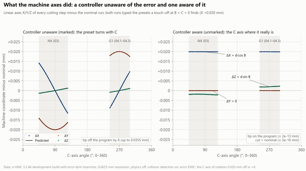
How far the linear axes moved from the nominal run, with the touch-off presets typed in both runs. Left: the controller unaware of the error (marked) moves by the preset difference turned with C, RY(−B)·RZ(−C)·d, so the tip leaves the program. Right: the controller aware of it (unmarked) moves at every cutting step X by d·cos B (about +0.020 mm), Z by d·sin B (NX −0.0017 to −0.0023, G1 +0.0018 to +0.0023 mm) and Y not at all, so the tip is back on the program. Dots are measured, black lines predicted. The vertical axes are symmetric. A HiNC 3.2.46 development build with error-term branches.
NX (03), the Diff in the front view. The picture alternates in place between two runs on the same machine with EX0C: the controller unaware of the error (marked) and aware of it (unmarked). The aware controller cuts back to the nominal, and its picture equals the control run's pixel for pixel. Diff colour scale ±0.03 mm (red = cut too deep, blue = material left, green = 0, both signs weighted alike); 0.0625 mm; a HiNC 3.2.46 development build with error-term branches.
G1 (04.1–04.3), the Diff in the front view, alternating in place: the controller unaware of the error (marked) and aware of it (unmarked). Scale, grid and build as above.
The control run and Diff–Stats
The control run (switch off, with the Diff) is the nominal run played again, and its per-step series equals the nominal run's bit for bit. Its four pictures (two sets, front and isometric views) have 100 % of their pixels within ±0.001 mm. They equal the unmarked run's four pictures byte for byte.
Diff--Stats of the eight runs with a Diff
| Run | Reported leaves | Surface leaves before comparison | Expanded on demand | New nodes | NaN leaves | Measured wires | Unmeasured wires | Target triangles |
|---|---|---|---|---|---|---|---|---|
| NX, marked | 1,423,270 | 1,396,005 | 19,343 | 46,608 | 164 | 5,602,677 | 4,757 | 2,791,548 |
| NX, control and unmarked | 1,422,853 | 1,395,788 | 19,278 | 46,343 | 0 | 5,602,407 | 516 | 2,791,548 |
| G1, marked | 1,421,697 | 1,394,641 | 19,053 | 46,109 | 0 | 5,602,460 | 2,929 | 2,789,554 |
| G1, control and unmarked | 1,421,942 | 1,394,793 | 19,097 | 46,246 | 1 | 5,603,733 | 538 | 2,789,554 |
| NX, marked, trimmed (0.25 mm) | 1,044,810 | 936,237 | 53,786 | 162,359 | 169 | 4,104,514 | 2,890 | 1,868,266 |
| G1, marked, trimmed (0.25 mm) | 1,077,674 | 913,457 | 72,603 | 236,820 | 0 | 4,237,837 | 1,764 | 1,829,980 |
The nominal runs make no Diff. In both sets, the control and unmarked runs agree in all eight numbers. Of the six 0.0625 mm runs, the most NaN leaves are 164 (NX marked, 0.012 % of the reported leaves). The 0.25 mm NX marked run has 169 (0.016 %).
The tool and its holder
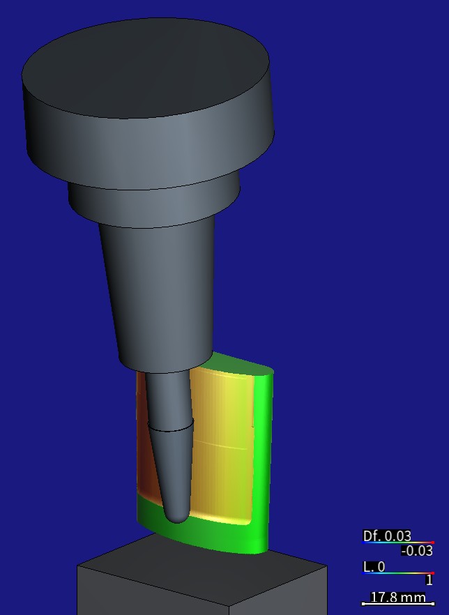
The part the G1 run cut with error terms on and the error marked. The base case's parking program
pose-g1-bottom-pass.h (the G1 copy of 04.3 cut after block 46) was then played under the same typed
presets, and it stops the tool in the middle of the bottom pass (close-up). The tapered ball-end
cutter, its Ø11.4 neck and the shrink-fit holder are in view. The face carries the Diff colours:
yellow to red = cut too deep. Diff colour scale ±0.03 mm (red = cut too deep, blue = material left,
green = 0, both signs weighted alike); 0.0625 mm; a HiNC 3.2.46 development build with error-term
branches.
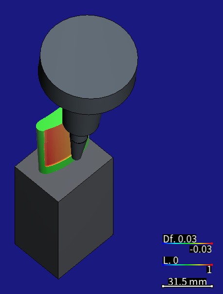
The same moment in the isometric view: the cutter, its neck and the shrink-fit holder in front of the face, which reads yellow to red by its Diff. Scale, grid and build as above.
The parking program retraces the bottom pass that is already cut, so it touches no material: 381
steps, 205.3 s, Finished, with Play-Touch--None reported. The Diff in these pictures is therefore
what the G1 marked run cut.
What the runs cost
All runs used private instances of a HiNC 3.2.46 development build with error-term branches, on the shared 32-thread server.
| Play | Grid | Steps | Wall time | VmHWM |
|---|---|---|---|---|
| NX nominal, trimmed | 0.25 mm | 2,410 | 30.0 s | 2.57 GiB (cumulative on one instance) |
| NX marked, trimmed | 0.25 mm | 2,410 | 140.3 s | 4.20 GiB (cumulative on one instance) |
| G1 nominal, trimmed | 0.25 mm | 2,011 | 25.0 s | 5.68 GiB (cumulative on one instance) |
| G1 marked, trimmed | 0.25 mm | 2,011 | 130.2 s | 6.10 GiB (cumulative on one instance) |
| NX nominal | 0.0625 mm | 2,410 | 55.1 s | 3.40 GiB |
| NX control | 0.0625 mm | 2,410 | 275.5 s | 4.60 GiB |
| NX unmarked | 0.0625 mm | 2,410 | 285.5 s | 5.13 GiB |
| NX marked | 0.0625 mm | 2,410 | 285.5 s | 5.64 GiB |
| G1 nominal | 0.0625 mm | 2,011 | 55.1 s | 3.33 GiB |
| G1 control | 0.0625 mm | 2,011 | 280.6 s | 4.46 GiB |
| G1 unmarked | 0.0625 mm | 2,011 | 280.5 s | 5.24 GiB |
| G1 marked | 0.0625 mm | 2,011 | 250.4 s | 5.31 GiB |
| Holder picture (parking program) | 0.0625 mm | 381 | 205.3 s | not recorded |
- VmHWM is the process's high-water mark of resident memory, converted from bytes as GiB =
bytes ÷ 2³⁰.
- Each full run started on a restarted instance, so its VmHWM is that run's own peak, including the Diff, the export and the stock record.
- The four trimmed runs ran one after another on one instance, so their values are the cumulative peak up to that point.
- The plan's stop line, 30 GB a run, is in GB (bytes ÷ 10⁹). The highest run, NX marked, reached 6.05 GB.
- Wall time runs from the start of the play to the first poll that read
Finished. So it includes the Diff, the export and the stock record after the play. The nominal runs make no Diff and took 55.1 s; the six runs with a Diff took 250.4–285.5 s. Other plays were running on the server, so the agent did not separate the parts of the time. - In all, the eight full runs ran from 21:18:06 to 21:48:58 on 2026-10-06. That is about 31 minutes including the restart before each run, and 1,768 s of wall time in total. The four trimmed runs took 325.5 s, and the holder picture 205.3 s.
- Against the design's estimate.
- Full runs: the design estimated 2–3 minutes a run and a peak of at most 15 GiB. Measured: 0.9–4.8 minutes and at most 5.64 GiB.
- Trimmed runs: it estimated about 20 s and at most 6 GB a run. The two with a Diff took 130–140 s, and the instance reached 6.55 GB cumulatively.
- The stop line, 30 GB a run, was never reached.
What it means
For a machining engineer.
- A C-axis centre only 0.020 mm off moves this blade's whole face by 0.010–0.029 mm under
M128. The NX program's blade comes out thicker, the G1 program's thinner. A touch-off takes out the offset only at one pose, C = 0, and the flank milling turns C 45° or more away from it. - Two programs on opposite B/C solutions get the error with opposite signs. So when two programs cut differently on one machine, the programs are not necessarily to blame. First check whether the machine's kinematics are calibrated. Here is the clue: a wrong tool radius moves both programs the same way, while a wrong C-axis location moves them in opposite ways.
- The paper's G1 blade lies within ±0.01 mm. On this uncalibrated machine, 20 of its 25 points would fall outside that band, by the derivation here.
- A controller with calibrated kinematics takes the whole error back out. The only cost is that, while cutting, the linear axes stand 0.020 mm from their nominal positions at every step.
- In HiNC, a constant error measured on a machine can go into its model. Its shape and size on your own part then show before the part goes on the machine.
For a teacher or a student.
- How a rotary axis' location error becomes the tip offset (I − RZ(C))·d, and why it depends on C alone, not on B or on where the tool is.
- Why “the tool is nearly upright” is not “the error is as small as on three axes”. B tilts only 5–6.6°, but C turns 45–125° away from the touch-off pose (61–116° for G1, which takes the short way). So the part shows the location error of C multiplied by 0.77–1.77.
- The face keeps only the part of the offset along its normal. That is why NX's deviation grows from +0.012 to +0.026 mm along the chord.
- How a real machine's touch-off differs from HiNC's P0 on the nominal chain, and which run to compare machine coordinates with.
For someone weighing the approach.
Cost. The build and twelve plays, plus one more play for the holder picture. The eight full runs took about 31 minutes of server time, at most 5.64 GiB a run.
Predictions. The plan's predictions were committed before the plays:
- the tip formula holds step by step to the order of 10⁻¹³ mm;
- the five chord segments come within 0.0010 mm of the prediction;
- the mean shifts at the paper's 45 points measured +0.0181 and −0.0204 mm, against the plan's +0.018 and −0.020 mm.
On average, the designer's per-point predictions differ from the measured shifts by less than 0.00003 mm; point by point, by at most 0.00047 mm (NX) and 0.00085 mm (G1). They were written before the plan but committed only after the plays, so the commit record cannot prove they came first.
Misses. Where a prediction missed, or could not be checked as written, the page states what was measured: what to compare the machine coordinates with, no step at C = 0 under
M128, and NX's 98.99 % over the whole box.
Honest limits
- One error only. This case has only EX0C. A real five-axis machine has several errors at once, such as a location error of the C axis in Y, location errors of the B axis, and the squareness between B and C. An error term holds only a constant error. It cannot express errors that vary with position (positioning, straightness, volumetric error tables), backlash, servo mismatch or thermal growth (Machine Geometric Error).
- The size and the sign are chosen. 0.020 mm is a typical value, and +X was chosen too. δ is linear in d, so with −X the two programs would swap signs at the same size: NX thinner, G1 thicker.
- The machine is not the paper's. The paper names no machine. This is the base case's own generic B/C table-table machine.
- The stock is a stand-in. Every run starts from the stand-in, grown 0.484 mm out of the design
surface, without 01 and 02. On a real machine, 02 (
M128, C 0–360°) carries the same error. But the finishing removes all the material on the face, so 02's error does not affect the face (derived). The strip at the bottom of the box, Z −43 to −41.6, counts as stand-in and stays out of the band statistics. It holds 6,125 points at least 0.45 mm from the design surface:- 4,510 points that neither run's finishing cutter reached, the same stand-in surface in both runs;
- 1,615 points that the nominal run cut deeper than the marked one, which did not reach them or wiped off less than 0.034 mm. They keep at most +0.024 mm of material.
- Geometry only. Physics was off, so there is no cutting force or deflection. The base case was accepted with physics on.
- The touch-off is typed in. HiNC's P0 measures on the nominal chain, so it does not take the error in as a real touch-off does. The presets of the two runs with the error are derived, not measured by a touch-off in the simulation.
- The paper's 45 points “with the error” are derived, not a play (dilemma 10).
- The holder clearance is derived. At least 5.11 mm is the base case's 5.15 mm less the largest shift. It was not measured here; the only support is that HiNC's collision detection reported nothing.
- The control run has no mesh of its own. Its noise floor is judged on three pieces of evidence:
- the hue of the pictures (1° of hue = 0.00025 mm; dark or anti-aliased pixels can be a few degrees off);
- the per-step series;
Diff--Stats.
- How the face points are chosen. The choice depends on the base case's NURBS design-face grid (480 × 210, within 1 mm), and it treats points 0.45 mm or more from the design surface as stand-in. Another choice moves the segment medians at the 1 × 10⁻⁴ mm level. The mesh distance takes the 12 nearest triangles and shows artefacts near sharp edges (dilemma 8).
- Only G1 has a holder picture. The plan asked for one picture with the holder in view, so NX has no holder close-up.
- Gaps in the records. The records keep only warnings and above, so there is no
executedLineCountand no message below warning level. The record of the holder play was cut off after its first warning code, and its memory was not recorded. - The wall times were measured under load. Other plays were on the server. The status was polled every 5 s, so a wall time can be up to 5 s late. The trimmed runs' VmHWM is cumulative on one instance.
What a reader can take to their own case
- Put the error on a branch of its own, directly upstream of the axis it belongs to. Leave the axis' own branch, its values and its role as they were (Where an Error Term Goes).
- Type in every work offset a touch-off would find. HiNC's P0 measures on the nominal chain, while a real touch-off takes in the shift the error causes at its pose. When the programs run from more than one preset, as here, derive all of them from the same touch-off. Otherwise the programs no longer share one touch-off (Program Zero Alignment).
- Write the predicted tip offset down in closed form before the first play, and check its sign on the first cutting step. A rotary axis' location error gives δ = (I − R(C))·d. The formula has no constant term, so a wrong or ignored work offset shows up as a constant difference on every step.
- Compare every step, not only the cutting steps, and group the misses by program line. Here the
misses were the tool changes, the first approach after
M128and the return of the rotary axes, all in the air. - Let two programs on opposite rotary solutions tell a machine error from a tool error. A C-axis location error moves their faces in opposite ways; a wrong tool radius moves them the same way.
- Compare machine coordinates with the run that has the same work offsets. Only then does “the switch does not change the machine coordinates” hold.
- Make the nominal cut the ideal geometry, and judge only where the finishing cutter reached. The Diff then shows the error, not the toolpath's own marks, and stand-in surface the cutter never touched does not count as a result.
- Quote percentiles, not extremes, of a mesh distance. At edges and pass boundaries, the extremes can be artefacts of the grid or of the distance search.
- Play a picture's parking program under the work offsets of the run it shows. Otherwise it can cut the recorded stock again.
- Try the real value before enlarging an error. Here a 0.0625 mm grid read deviations of 0.01–0.03 mm, 16–46 % of a cell, and the swept-cutter prediction agreed within 0.0004 mm on 99 % of the points.
Source and licence
- Source. K. Rajain, G. Gómez Escudero, M. Bizzarri, H. Gonzalez Barrio, A. Calleja-Ochoa,
L. N. López de Lacalle, M. Barton, High-quality smooth finishing of blade-like geometries via G1
multi-pass 5-axis flank CNC machining using conical cutting tools, Zenodo (2025) —
https://zenodo.org/records/15830311; described in K. Rajain et al., The International Journal
of Advanced Manufacturing Technology 136, 4383–4397 (2025),
https://doi.org/10.1007/s00170-024-14898-6. If the links move, search for
zenodo 15830311or the title. - What this study uses from the data set:
03.Finishing_NX.has published, and the base case's copies of04.1–04.3with two lines changed;- the values of the 45 labelled points on the deviation map
dimentional_deviation_blade.png, as the base case read them; - the blade's NURBS surface, which the base case placed and made into a solid. Here it is used to pick the face vertices.
- Licence. The data set is licensed Creative Commons Attribution 4.0 International,
https://creativecommons.org/licenses/by/4.0/, and provided as-is, without warranty.
- The published article is not open access.
- The few facts on this page that come from the paper are taken over from the base case: the 60 × 50 × 60 mm block, the AISI 1045 material, and that the paper names no machine and does not say how its measurement was registered.
- The base case read them in the authors' submitted version in the BCAM repository, https://bird.bcamath.org/handle/20.500.11824/1905 (CC BY-NC-SA 3.0 ES). That version was read and not kept.
Attribution, as the base case's source record gives it:
NC programs, blade models and deviation map: K. Rajain, G. Gómez Escudero, M. Bizzarri, H. Gonzalez Barrio, A. Calleja-Ochoa, L. N. López de Lacalle, M. Barton, “High-quality smooth finishing of blade-like geometries via G1 multi-pass 5-axis flank CNC machining using conical cutting tools”, Zenodo (2025), https://zenodo.org/records/15830311; described in K. Rajain et al., The International Journal of Advanced Manufacturing Technology 136, 4383-4397 (2025), https://doi.org/10.1007/s00170-024-14898-6. Licensed CC BY 4.0 (https://creativecommons.org/licenses/by/4.0/), provided as-is and as-available without warranties (CC BY 4.0 Section 5). Changes: the three G1 programs are played from copies with two lines changed (TOOL CALL 0 -> TOOL CALL 22; CYCL DEF 7.0 -> CYCL DEF 7.0 DATUM SHIFT); blade_full.obj was placed in the programs' frame and meshed into a closed solid; the map's labelled points were located on the image; for pictures only, 03 and the G1 copy of 04.3 were cut short so that a play ends in the middle of the bottom pass.
What this study changed:
- No program was changed further. The holder picture's parking program,
pose-g1-bottom-pass.h, is the G1 copy of 04.3 cut short for pictures, which the attribution names. - The simulated machine gained the error term EX0C. Its place, size and sign, and the touch-off presets, are the agent's choices.
- No picture of the paper or of the data set is reproduced here. Every picture is a HiNC capture. The charts are drawn from HiNC's per-step results and cut meshes, and from the labelled values on the data set's deviation map.
- Everything is simulated; no blade was cut. This site offers no download: the reader fetches the originals from Zenodo.
See Also
- BCAM Blade: Two Five-Axis Flank Finishes Told Apart Before the Cut — how the blade, the machine and the two finishes were set up and accepted
- Building Virtual Machine Tools: Error terms — what a mark changes, the Enable Error Terms switch, and work offsets on a machine with error terms
- Kinematic Topology: Error-Term Branches — the nominal chain the controller solves, and what it can see
- Machining Issues Outside the Model: Machine Geometric Error — the machine errors the model leaves out
- Heidenhain Support —
M128, theCYCL DEF 247preset and theCYCL DEF 7shift on top of it - Geometry Validation — the geometry difference, its detection radius and its colour scale
- Program Zero Alignment — P0, and typing in a measured work offset
- Showcase — the other cases, and how a case page reads