A CubeSat Side Panel on a Z Axis 0.2 mrad out of Square with Y: Milled Flat, Its End Faces Lean Whole; Drilled on Edge, Its Holes Lean while Their Mouths Stay
SpaceTeamSat1 (STS1) is the TU Wien Space Team's 1U CubeSat, and its structure is six Al 7075 plates. In the STS1 case an AI agent built that structure into HiNC: its own 2.5-axis CAM, 24 clampings and their Fanuc programs, each clamping played on the stock record the one before it left, accepted at 0.125 mm. This page takes three of the five clampings of one side panel, CS_Yminus, and gives the case's three-axis machine one geometric error: its Z travel is out of square with the table in the Y–Z plane by 0.2 mrad, so that the tool tip moves 0.04 mm toward +Y over 200 mm of travel. That is the limit a light milling machine's factory inspection allows (Tormach 1100M inspection sheet TD10547, item G6a, 0.04 mm per 200 mm), not a typical value.
The error sits on one marked error term directly upstream of the Z axis. Not one line of the programs was changed. The same error reads two ways on this plate:
- Milled flat (OP1). The stock lies in the vise and the tool comes down from above. Every face toward ±Y — the two end faces, the end bars' inner faces, the corner blocks' end faces — is cut by the side of the tool, layer by layer. With the Z travel leaning, each layer's wall moves toward +Y by its own depth, so the whole face shifts and leans by θ. The floors take the tilt of the tool's bottom.
- Drilled on edge (E2, E3). The plate stands in the vise and the holes go into its end faces. The touch-off is on the end face, so the hole mouths do not move; the holes follow the leaning travel and move toward the part's +z, the side of the end bar's 0.85 mm wall, as they go deeper.
The real value leaves from a few tenths of a micrometre to about 3.2 µm on the part, so a second set was played at ten times the error, 2 mrad, as a display value, in folders of its own; every number below is given for both. Each clamping was played with the error terms off (the nominal run, whose cut is the ideal geometry of every comparison), off again with a Diff (the control, for the noise floor) and on with the error marked (the controller does not know it). What came out:
- The tool tip. On every step of every on run (E2 4,535, E3 5,251 and OP1 313,787 paired steps) the tip's offset lies on δ = (0, −Z·sin θ, −Z·(1 − cos θ)) within 2.54 × 10⁻¹³ mm, where Z is the nominal tip's program Z: 0 at the touch-off face, more toward +Y the deeper. Every step's machine coordinates are the nominal run's.
- The end faces, milled flat. The −Y end face is cut too deep all over and the +Y end face keeps material, more toward the bottom: the end bars read ∓2.03 / ∓20.31 µm on their upper band and ∓2.77 / ∓27.69 µm on their lower band (0.2 / 2 mrad; predicted ∓2.03 / ∓20.3 and ∓2.77 / ∓27.7). Every 0.5 mm of height, from the corner blocks' top at z 14.6 down to z 0.5, lies on the predicted line ∓(15.9 − z)·sin θ.
- The inner faces and the floors. The −Y end bar's inner face, facing the window, keeps +2.39 / +23.92 µm, and the +Y one is cut −2.39 / −23.94 µm too deep (predicted ±2.40 / ±24.0). The corner-block tops, finished last by a D6, read an almost even −0.588 / −5.873 µm from the tool's tilted bottom (predicted −0.59 / −5.9); the rail's side facing −X reads 0.
- The holes, drilled on edge. The hole axes move toward the part's +z by 2.000 µm per millimetre of depth (the M3 at 2 mrad; the M4 1.995 µm) and extrapolate to −0.10…+0.13 µm at the end face: the mouths stay and the holes lean. The M4 hole's top is cut −1.10 / −11.00 µm too deep in its deep stretch and its bottom keeps +1.06 / +10.63 µm (predicted ∓1.06 / ∓10.6); E3's M3 hole top reads −1.67 / −16.98 µm (predicted −1.63 / −16.3). The counterbore floor tilts with the tool's bottom, material left on one side and cut too deep on the other (+2.78 / −3.22 µm at 2 mrad, predicted ±3.2).
- Linearity. In the 20 boxes that read at both values, the 2 mrad median is 9.925–10.169 times the 0.2 mrad one.
- The control and the unmarked run. The controls' tips and machine coordinates equal the nominal runs' at every step, and their cuts deviate by about 10⁻¹⁰ mm. One E2 run played with the mark cleared, the controller knowing the error, equals the on run at every step: a plain three-axis program cuts the error in, marked or not.
- The cost, on a shared 32-thread server: 4,535 / 5,251 steps, 5–30 s and 1.23–2.33 GB per E2 / E3 run; about 314,000 steps, 666–741 s and 4.13–5.75 GB per OP1 run.
Everything here is simulated; no part was cut.
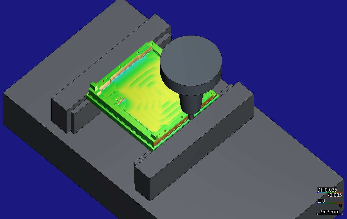
The stock the OP1 run with the error terms on recorded (2 mrad, the ×10 display value), put back on
the canvas with its Diff, and the pose program pose-op1-t2.nc played on it: the T2 D6 end mill in
its SF6 shrink-fit holder stops 0.2 mm beside the −Y end face at the end bar's mid-height and touches
nothing (Play-Touch--None). Diff colour scale ±0.035 mm (red = cut too deep, blue = material left,
green = 0, both signs weighted alike); 0.125 mm; a HiNC 3.2.46 development build with error-term
branches.
| CS_Yminus at 0.125 mm on a HiNC 3.2.46 development build with error-term branches, 0.2 / 2 mrad | Predicted | Measured |
|---|---|---|
| Tip minus the nominal tip minus δ, every paired step of the six on runs | 0 (the plan allowed 10⁻⁹ mm) | at most 2.54 × 10⁻¹³ mm |
| Machine coordinates, on against nominal | the same | the same at every step |
| Offset at program zero of an affine fit of the tip offset | 0 (allowed 10⁻⁹ mm) | at most 8.44 × 10⁻¹⁴ mm |
| −Y end bar's end face, upper / lower band (µm) | −2.03 / −20.3; −2.77 / −27.7 | −2.029 / −20.313; −2.768 / −27.687 |
| −Y corner block's end face, top / bottom (µm) | −0.62 / −6.2; −2.74 / −27.4 | −0.629 / −6.310; −2.731 / −27.311 |
| End bars' inner faces, −Y / +Y bar (µm) | ±2.40 / ±24.0 | +2.394 / +23.924; −2.394 / −23.937 |
| Corner-block top (µm) | −0.59 / −5.9 | −0.588 / −5.873 |
| Rail side facing −X | 0 | 0 / 0 |
| Hole-axis slope, M4 / M3, 2 mrad | sin θ = 0.002 ± 15 % | 0.0019945 / 0.0019998 |
| Hole axis extrapolated to the end face, M4 / M3, 2 mrad | ≤ 0.15 × the deepest slice | −0.095 / +0.126 µm (deepest 15.36 / 19.62 µm) |
| M4 hole, top / bottom of the deep stretch (µm) | ∓1.06 / ∓10.6 | −1.102 / −10.996; +1.058 / +10.630 |
| M4 hole top at the mouth against its deep stretch, 2 mrad | at most 0.3 | 0.158 |
| 2 mrad against 0.2 mrad, the 20 boxes that read at both | 10 ± 1.5 | 9.925–10.169 |
| Control against nominal, tip and machine coordinates | 0 | 0 at every step |
| Server time / peak memory of an OP1 run | — | 665.7–740.8 s / 4.13–5.75 GB |
The case
The STS1 case tells how the agent went from the team's published STEP files and 13-sheet drawing set to its own 2.5-axis CAM, 24 clampings over the six plates, the Fanuc programs and 24 HiNC projects, each clamping played on the stock record the clamping before it wrote, and accepted at 0.125 mm (source and licence below). The side panel CS_Yminus, 91.4 × 94.0 × 14.9 mm from a 95.4 × 98.0 × 23.9 mm stock with 25 holes, has five clampings: OP1 (the stock flat in the vise, the top half milled), OP2 (turned over onto a nest on a sub-plate), and E1–E3 (the plate on edge in the vise, the end faces and the sides drilled). Its machine was built as designed, with no error. This page adds one geometric error to it and asks what a Z axis out of square does to the same plate when it is milled flat and when it is drilled on edge. What the agent was given:
- The base case's projects and programs.
- OP1: the stock in the vise, program zero at the centre of the stock top,
G54(−400, −250, −486.09999946062453). Eleven stage programs, one tool each: roughing with a D16, a D6, a D4 and a D2 end mill, semi-finishing with the D6, D4 and D2, a D4 ball-end mill in the coves, and three drills (D1.6, D2.4, D2.5). The D6 (T2) sits in an SF6 shrink-fit holder. - E2: the plate on edge, the tool coming from the part's −Y, program zero on the −Y end face,
G54(−400, −250, −446). A D1.6 drill for two M2 holes, a D3.3 drill for the M4 hole, a D4 end mill milling round a D5.5 H7 seat, and a D5.5 H7 face reamer. - E3: the same from the part's +Y, on the +Y end face, with the same
G54. The D1.6 drill for two M2 holes, a D2.5 drill (T14, in an SF4 shrink-fit holder) for the M3 hole, the D4 end mill plunging the D4 counterbore round it, and the face reamer for the seat. - All plain three-axis Fanuc programs:
G54,G43,G81/G83drilling cycles; no RTCP, no tilted plane, no CL. - The stock records: the five clampings of the plate hand the stock on, OP1 → OP2 → E1 → E2 → E3, each reading the record the one before it wrote.
- OP1: the stock in the vise, program zero at the centre of the stock top,
- The machine. HiNC's three-axis skeleton
Empty-wXYOZSt.default.mt, shared by the base case's 24 projects: the table moves in X and Y, the head in Z, with a spindle role onZ→S. It has no shapes. - HiNC's error terms. An axis or the spindle of the machine chain can be given an error term, a static branch of its own just before the axis's branch: it carries a measured error rather than part of the design. The controller, which turns NC into machine coordinates, solves on the nominal chain, taking the marked branches as absent; while the project's Enable Error Terms switch is on, the simulated machine keeps them as it moves, cuts and checks collisions. So the error is cut into the part, as on a real machine whose controller does not know it. Each step's machine coordinates are the same with the switch on and off; the tool tip and the cut differ. Without RTCP or a tilted plane, every error in the chain is cut into the part, marked or not (What a mark changes).
- Touch-off and P0. HiNC's P0 measures program zero on the nominal chain. On a real machine,
the
G54found by touching off already holds the constant shift the error causes at the touch-off pose (Work offsets on a machine with error terms). - A placement rule. HiNC's product owner ruled on 2026-10-06 that an error term goes only directly upstream of a role branch, an axis X … C or the spindle, with one new anchor for each error.
- The request. HiNC's product owner asked for error-term showcases built on earlier cases, product cases and paper cases alike, with the heavy runs on a shared server.
What nothing states:
- How far this machine's Z is out of square. No machine was measured. The agent took the limit of a published factory inspection sheet of a light milling machine, 0.2 mrad, and the direction “the Z travel and the tool turned about +X”.
- Which clampings show it. The plate has five; the agent chose the three that read the error two different ways, and kept clear of E1, a clamping the base case places 120° about a diagonal, where HiNC has a known defect (dilemma 1).
- Where the pivot goes so that
G54need not change, for two touch-off heights (dilemma 4). - Whether a 0.125 mm grid reads a few tenths of a micrometre (dilemma 5).
What is new here:
- One error, two readings. The same squareness leans the faces of the flat clamping and the holes of the edge clampings, and leaves the edge clampings' touched-off end faces where they were.
- The touch-off point as the zero. The deviation is 0 where the tool touched off and grows with the distance below it: 15.9 mm of plate below the stock top in OP1, 8–10 mm of hole below the end face in E2 and E3.
- A chain of five clampings. The edge clampings start from a stock record another clamping wrote, and the error-term runs read and write such records too (dilemma 1).
What the agent built
Each value is marked read (from the base case or the build record), derived (computed from what was read) or chosen (the agent's decision). θ is the Z travel's squareness to Y.
| Value | Source | |
|---|---|---|
| Meaning | The Z travel, with the head, the spindle and the tool on it, is out of square with the table in the Y–Z plane, the squareness of Z to Y in ISO 230-1's terms. For every 1 mm the tool goes down its tip moves θ mm toward +Y: 0.2 µm per mm at the real value | chosen: the kind of error and its direction; derived: the amount per mm |
| Size | θ = 0.2 mrad = 0.011459155902616465°, 0.04 mm per 200 mm: item G6a of the Tormach 1100M factory inspection sheet TD10547 (spindle centreline to table, along Y, 0.04 / 200), which also meets its item G5a (head travel to table, along Y, 0.035 / 150 = 0.233 mrad). A light milling machine just at the edge of its factory acceptance | chosen: the published limit, not a measurement of any machine |
| Display value | ×10 = 2 mrad = 0.11459155902616465°, in folders of its own, marked as the display value wherever it is shown | chosen |
| Where | Directly upstream of the Z axis branch (base→Z), with a new anchor Zerr. base→Zerr is named YZsq and carries a Static Rotation about (1, 0, 0), marked as an error term. The Z axis' Dynamic Translation (axis (0, 0, 1)) moved whole onto Zerr→Z, and Axis Z was bound to it again; the spindle NewAnchor-006 (Z→S) and every other branch are unchanged |
chosen: following the owner's ruling of 2026-10-06 |
| Pivot, edge clampings (E2, E3) | (0, 0, 554) in base coordinates: G54 Z −446 plus the tooling location's 1000, the tool tip at the touch-off on the end face |
derived |
| Pivot, flat clamping (OP1) | (0, 0, 513.9000005393755): G54 Z −486.09999946062453 plus 1000, the tool tip at the centre of the stock top |
derived |
| Why only Z matters | The tool side base→Zerr→Z→S→t carries no X or Y axis, so in base the tip always stands on the spindle line x = y = 0: the pivot's X does not change the result, and its Y must be 0 |
derived |
| The chain | Table side O→base→X→Y→w, tool side base→Zerr→Z→S→t |
read: the topology read back from the six projects after the build |
| Work offset | Every run uses the project's own G54; nothing is typed in |
derived: the deviation at the touch-off point is 0 (dilemma 4) |
| Folders | One error, two pivots, two values: four project folders, each with its own machine file — Edge/ and Edge-x10/ (the E2 and E3 projects, sharing the folder's machine file and stock records), Flat/ and Flat-x10/ (OP1) |
chosen |

The machine-tool cluster in the Topology column of the Equipment page. The error term YZsq is the
branch base→Zerr, drawn with the orange Error term badge; the Z axis (Machine Tool · Axis Z) sits
downstream of it on Zerr→Z, and the spindle NewAnchor-006 is unchanged. A HiNC 3.2.46
development build with error-term branches, English interface.
Where the tip goes: the prediction written in the plan.
- In base coordinates the tip stands at (0, 0, Z_MC + 1000 − H), with H the tool length: the spindle turns about (0, 0, −1) with its pivot at (0, 0, 1000), the tip on its axis, and the tooling location adds (0, 0, 1000). The program axes point the way base does in all three clampings.
- The error turns the tool side by θ about the pivot c, so the tip goes to R(tip − c) + c with R = R_X(θ), and its offset is δ = (R − I)·(0, 0, Z) = (0, −Z·sin θ, Z·(cos θ − 1)), where Z is the nominal tip's program Z.
- δ depends on Z alone, not on X, Y or the tool: 0 at the touch-off height, toward +Y below it and toward −Y above it.
How far the part's faces move: the plan's prediction.
- OP1, in part coordinates (z_p = z − 15.9027): a wall cut by the side of the tool moves by δ = (0, (15.9027 − z)·sin θ, ≈ 0). A face toward −Y is cut too deep and a face toward +Y keeps material, by (15.9027 − z)·sin θ, 0 at the stock top.
- E2 and E3: the part's +z is the machine's +Y. At depth d the hole axis moves toward the part's +z by d·sin θ: the hole's top is cut too deep and its bottom keeps material, and the mouth, on the touch-off face, does not move. E2 drills from the −Y end and E3 from the +Y end, and both holes climb toward +z, so the two axes make a V mirrored about the plate's mid-plane.
- The floors cut by a flat-bottomed tool tilt with the tool's bottom: lowest on the −Y side, by R·sin θ.
The runs:
| Run | Project | Enable Error Terms | YZsq |
Purpose |
|---|---|---|---|---|
| t-e2x-nominal | E2, 2 mrad folder | off | marked (not in effect) | trimmed: the nominal cut |
| t-e2x-on | E2, 2 mrad folder | on | marked | trimmed: the formula and the signs |
| t-e2x-unmarked | E2, 2 mrad folder | on | not marked | trimmed: the controller knows the error |
| t-e2x-control | E2, 2 mrad folder | off | marked (not in effect) | trimmed: the noise floor |
| t-op1x-nominal / t-op1x-on | OP1 stage 1 (the D16 roughing), 2 mrad folder, 0.25 mm | off / on | marked | trimmed: the heavy clamping's first stage |
| f-e2-nominal / f-e3-nominal / f-op1-nominal | 0.2 mrad folders | off | marked (not in effect) | the ideal geometry of every comparison |
| f-e2-control / f-e3-control / f-op1-control | 0.2 mrad folders | off | marked (not in effect) | the noise floor |
| f-e2-on / f-e3-on / f-op1-on | 0.2 mrad folders | on | marked | the real value |
| f-e2-onx10 / f-e3-onx10 / f-op1-onx10 | 2 mrad folders | on | marked | the display value |
Common to every run:
- A 0.125 mm grid, the base case's acceptance grid (0.25 mm for the trimmed OP1 stage), physics off, collision detection on.
- The stock chain of the edge clampings. E2 starts from the stock OP2 recorded in the base case's acceptance (dilemma 1) and E3 reads the record E2 wrote last; the on and nominal runs read the same input, so the only difference comes from E2 and E3 themselves (OP1 and OP2 are not played with the error). In each folder E3 plays right after the E2 of the same mode.
- OP1 from the stock box: the base case's stage records are disabled, and the eleven stage programs play in one run.
- The ×10 runs are compared with the 0.2 mrad folder's nominal and control: a run with the error terms off does not read the error's value, so its cut is the same in both folders.
- The Diff (Geometry Validation): the ideal geometry is the
same clamping's nominal cut, with a detection radius of 1 mm; the colour scale (
DiffVisualRadius) is ±0.005 mm on the edge clampings and ±0.035 mm on OP1 at 2 mrad, a tenth of that at 0.2 mrad. Every run with a Diff recorded its stock and exported its cut.
How the agent managed the work
- A design read by other agents before the plan. Four read-only agents read the design from four sides, the kinematics, the tool's behaviour, the criteria and the feature predictions, and found errors in it before anything was played (dilemma 9).
- Criteria and predictions first. The plan, its predictions and ten criteria were committed at 01:20:17 on 2026-10-07; the first play started at 01:20:28.
- The build. The agent's tools saved each base project as a new error-term project in its folder
and changed it through the web API only:
ZerrandYZsqinserted and the branch marked, the Z axis moved and bound again, the grid set to 0.125 mm, physics off, the stock records kept or disabled as each run needs. Each of the six projects was then reopened and its chain read back. - Trimmed runs first. T1, the E2 clamping at 2 mrad played nominal, on, unmarked and control, checked the build, the per-step formula, that the machine coordinates equal the nominal run's, the holes' signs and the marked-against-unmarked question. T2, OP1's first stage (the D16 roughing) at 0.25 mm, checked the heavy clamping's formula and offset at program zero.
- A change after the first round, written down before the rerun. The first round of the full edge runs started E2 from E1's stock record, as the base case chains them, and E3's own hole group came out with no vertex in its boxes. A trial from OP2's record fixed it, the change went into a dated section after the plan's text (committed at 01:41:09), and T1 and the edge runs were all played again from 01:42:30 (dilemma 1). OP1 and T2 were not affected.
- One run at a time, a restarted instance for every run. Each run loaded its project from file on a freshly restarted instance, so each VmHWM is that run's own peak. The edge runs, under a minute each, ran at once; the OP1 runs, 11–12 minutes and up to 5.8 GB each, waited for their turn on the shared server and ran from 17:08 to 17:56.
- The stock records checked before every play. When a stock record a run should read is missing, HiNC logs one message and plays from the stock box, so the nominal and the on run would both start wrong and the comparison would not show it. Before each play the agent's tools check that every record the run reads is there and log its size and time: every E3 read a record written during the E2 run of its own mode, and every E2 read the same OP2 record of 93,515,940 bytes.
- Step by step. The E2 and E3 runs have the same step count as their nominal runs and were lined up by step index; the OP1 on runs have one or two steps more, so their steps were paired by program file and line (dilemma 8).
- Every number from the records. The agent's analysis scripts compute every number on this page from the run records and the exported cuts, and keep each number with its source.
- Pictures in both interface languages, from the recorded stock put back on the canvas, not from a replay: the Diff from five cameras on OP1 and from above on E2 and E3, two pose programs that bring the tool and its holder into view, and the topology graph.
- Where a person stepped in. HiNC's product owner asked for error-term showcases built on earlier cases and ruled where an error term may go. The error, its size and direction, its pivots, the clampings, the predictions and the criteria are the agents' own: the designer agent worked them out, the review agents corrected them, and the agent that ran the case wrote them into the plan.
The criteria as committed before the first play (n_box is a box's noise floor, criterion 4):
| # | Criterion |
|---|---|
| 1 | Build, judged on the six projects reopened: the topology O→base→Zerr→Z→S→t; YZsq (base→Zerr) a marked Static Rotation about (1, 0, 0) whose angle and pivot read back as the case file gives them (within 10⁻¹²); Z (Zerr→Z) the original Dynamic Translation, bound to Axis Z; X, Y, the spindle NewAnchor-006, the two mounts and every other branch unchanged; the roles check empty; no load message on reopening; the case's files outside the error-term folder unchanged |
| 2 | Every run: Finished, more than 0 steps; every stage program with a path has contact steps (IsTouched, counted per stage); the on, control and unmarked runs' messages of warning level and above the same as the nominal run's, apart from Diff--TargetNotClosed and Diff--Stats; no collision, no stroke alarm, no rapid move cutting; the stock chain as planned |
| 3 | Tip, every paired step, the steps in the air included: |ΔMC| ≤ 10⁻⁹ mm between on and nominal; |Cl(on) − Cl(nominal) − δ| ≤ 10⁻⁹ mm; the offset at program zero of an affine fit ≤ 10⁻⁹ mm; control against nominal and unmarked against on the same at every step (≤ 10⁻¹²); where the step counts differ, steps paired by file and line |
| 4 | Noise floor: in each box, n_box = max(|p01|, |p99|) of the control's distance to the nominal cut, at least 0.1 µm |
| 5 | The 2 mrad boxes on walls, holes and signed floors (not H3 or F11, which belong to criterion 7): the median has the predicted sign and |median − predicted| ≤ 20 %·|predicted| + 2·n_box |
| 6 | The same boxes at 0.2 mrad: where |median| > 3·n_box, the same test, and median(2 mrad) / median(0.2 mrad) = 10 ± 1.5; a box below that is reported as below the noise floor, with its 2 mrad value divided by 10 |
| 7 | The touch-off face: at 2 mrad, |H3| ≤ 0.3·|H1| (the M4 hole's top at the mouth against its deep stretch); the zero box F11 |median| ≤ 3·n_box at both values |
| 8 | Floors: F12's median by criteria 5 and 6 (−0.59 / −5.9 µm), and the p01 and p99 of F12, F13 and H6 within their predicted ranges widened at each end by 20 % of the range plus 2·n_box |
| 9 | Hole axes at 2 mrad: for E2's M4 (axis x −30.5, z 4.3027, r 1.65, y −47…−39) and E3's M3 (axis x −41.35, z 4.3527, r 1.25, y 41.2…36.72), the slope of the fitted centre's z shift against depth = sin θ ± 15 %, and the shift extrapolated to the end face ≤ 0.15 × the deepest shift |
| 10 | Cost: steps, wall time and VmHWM of every run |
The dilemmas
Each one is told as its situation, the risk if it had been missed, how it was noticed, the resolution, and the evidence that the resolution held.
1. E1's stock record carried broken corner blocks: E2 starts from OP2's
- Situation. The base case's five clampings of the plate hand the stock on by records, and E2 read the record E1 wrote. The first round of the full edge runs did the same. E2's boxes round its M4 and M2 holes matched the prediction at both values, but in E3's own hole group, the M3 hole and its D4 counterbore, the four boxes held not one vertex, and the M3 hole's axis could not be fitted.
- Risk. E3's hole group is half of the edge story: without it the page would have one hole family instead of two, or a wrong reading of the one it has.
- How noticed. The boxes' vertex counts were 0. Sliced along the M3 axis, the nominal cut had the hole exactly where designed but only the half of its wall below the axis, and most of the plate's bottom face there was missing. Counted on the exported cuts, the edges used by one triangle only (open edges) numbered 6,289 on E2's nominal cut and 9,052 on E3's, gathered at the two corner blocks.
- Cause. E1 is one of the clampings the base case places 120° about a diagonal of the plate. HiNC has a known defect there, recorded in the base case: such a clamping reads no force, and the exported part has open edges round the features it cuts. E2 and E3 read its record and inherited the broken corner blocks; E3's hole group is drilled into the +Y one.
- Resolution. A trial started E2 from the record OP2 wrote in the base case's acceptance: the open edges fell to 726 on E2's nominal cut and 1,272 on E3's, and the M3 hole came out whole, 320 points per 0.5 mm slice, centred where designed. E1 drills side holes at z 11.75 that meet neither E2's nor E3's holes (at z about 4.35), so the edge runs now start E2 from OP2's record. The change went into a dated section after the plan's text, and T1 and the edge runs were all played again. The edge parts therefore lack E1's side holes; nothing measured depends on them.
- Evidence. The open-edge counts and places of the first round, the trial and the runs reported; the plan's dated section; every E2 run's log of the record it read (93,515,940 bytes, OP2's).
2. The first round's seat floor contradicted the prediction
- Situation. In the first round, box H6, the floor of E2's D5.5 seat, read a median of +1.75 µm at 2 mrad from 46 vertices, where the reviewers had derived about −1.2 µm from the toolpath.
- Risk. Taken at its word, the reading would have said the prediction was wrong; changing the prediction to fit it would have bent the plan to a broken mesh.
- How noticed. The box held far fewer vertices than a seat floor should.
- Cause. The same broken corner block: the seat lies in the −Y one.
- Resolution and evidence. From OP2's record the same box holds 1,081 vertices, with a median of −0.50 µm and p01 / p99 of −4.71 / +4.29 µm, where the reviewers' tool sweep gave −4.75 / +4.25. A box with far fewer vertices than usual is checked on the exported mesh before the prediction is doubted.
3. The flat floors of the edge clampings still export open
- Situation. From OP2's record, E2's and E3's exported cuts still have a few hundred open edges,
all on floors cut by flat-bottomed tools: the D5.5 seats (|y| 46) and E3's counterbore floor
(y 41.2). OP1's export has them too, 20,680 on its nominal cut, the largest groups at the corners
and along the edges of the uncut stock bottom (z −8). HiNC's Diff reports
Diff--TargetNotClosedon every on and control run, the ideal geometry not being closed, and over the runs 4–13 leaves it could not measure (NaN) and 9,950–21,533 wires it could not measure, against 2.50–4.01 million measured. - Risk. Boxes on those floors could read the holes of the mesh instead of the cut.
- How noticed. Counting the open edges of every exported cut after the trial.
- Resolution. Recorded as it is. The boxes on the counterbore floor, H9a and H9b, hold only 19 and 23 vertices but read as predicted (+2.78 and −3.22 µm at 2 mrad, predicted ±3.2); no other measured face lies on an open stretch. The observation, that edge clampings placed 90° and 180° also leave their flat floors open, was added to HiNC's defect record of the 120° placement.
- Evidence. The open-edge counts per exported cut; the boxes' vertex counts and readings.
4. Two touch-off heights, two pivots, so that G54 stays
- Situation. A real machine's touch-off takes into the work offset the constant shift the error causes at the touch-off pose; HiNC's P0 measures on the nominal chain and takes in nothing. This plate is touched off at two heights: on the stock top in OP1 and on the end face in E2 and E3.
- Risk. With one pivot for all three, at least one clamping's program zero would move by the distance between the touch-off heights times θ, the on and nominal runs would need different work offsets, and the Diff would charge the missing touch-off to the error.
- How noticed. While the design derived program zero's offset.
- Resolution. One pivot per touch-off height, each where the tool tip stands at its touch-off: the
end face at (0, 0, 554) and the stock top at (0, 0, 513.9). The deviation is then zero at the
touch-off point, and each project's own
G54is what a real touch-off would find. The price is two machine files, hence theEdgeandFlatfolders. - Evidence. The affine fit's offset at program zero is at most 8.44 × 10⁻¹⁴ mm over the six on runs
and T2; every run used its project's
G54, nothing typed in; the machine coordinates of on and nominal differ by 0 at every step.
5. 0.2–3.2 µm on the part: a display value beside the real one
- Situation. At 0.2 mrad the largest deviation on the part is about 3.2 µm, at the foot of OP1's end faces, 15.9 mm below the touched-off stock top; the hole mouths and the floors move only a few tenths of a micrometre. A grid cell is 125 µm.
- Risk. On the canvas the real value is a faint tint; boxes at a few tenths of a micrometre could sit in the noise.
- How noticed. In the design's estimate of each feature.
- Resolution. A second set at ten times the error, 2 mrad, in folders of its own and named as the display value wherever it is shown. Both sets were measured: 20 boxes read at both values; H9a, the counterbore floor's upper side, reads 0.28 µm at 0.2 mrad, below three times its noise floor (0.3 µm), and is reported as below the noise floor, with the 2 mrad value divided by 10 (0.278 µm), as the plan says. Most canvas pictures show 2 mrad; each has a real-value twin at a ten times finer colour scale.
- Evidence. The 2 mrad / 0.2 mrad ratios of 9.925–10.169; the real-value pictures look the same as the display-value ones (see the real value and the display value below).
6. The hole walls cannot be seen on the canvas
- Situation. HiNC's canvas has no section view: from above, a hole shows its mouth and its bottom, and the deviation is on its wall.
- Risk. A picture that cannot show which side of a hole deviates, or how deep, leaves the reader with the numbers alone.
- How noticed. Listed as a doubt in the design.
- Resolution. The holes are measured on the exported meshes: feature boxes, a map of the hole walls unrolled about their axes, and the axis fitted slice by slice. The canvas pictures show what can be seen, the end faces, the seat floor and the counterbore floor, and one picture brings the drill and its holder into the M3 hole.
- Evidence. The unrolled map and the axis chart below.
7. A partial slice at the M3 exit pulled the hole-axis fit
- Situation. The first fit of the M3 hole's axis gave a slope of 0.00116 and 6.3 µm at the end face, against the boxes' reading.
- Risk. A wrong slope would have failed criterion 9 on a correct cut, or passed a wrong one.
- How noticed. The fit disagreed with the boxes on the same wall.
- Cause. The centre is fitted per 0.5 mm slice of the wall, and the last slice ran past the hole's exit (y 36.72, where the M3 breaks into the window): 222 points, its centre 1.2 µm off in x and 5 µm off the line in z. The eight whole slices read 12.63, 13.62, … 19.63 µm, 2.000 µm per mm.
- Resolution. Only slices that lie wholly inside the hole are fitted (the M4's slices all do).
- Evidence. The M3 reads 0.0019998 and 0.13 µm at the end face.
8. The on runs make one or two more steps and touch more
- Situation. The two OP1 on runs have one and two steps more than the nominal run, and more contact steps: in stage 1, the D16 roughing, 51,291 nominal against 56,653 at 0.2 mrad.
- Risk. Lined up by step index, every step after the first extra one would be compared with the wrong partner.
- How noticed. The step counts differed.
- Cause. HiNC places the steps where the tool tip really moves, and the leaning tool made a line one step longer. With its flat bottom tilted, each pass's low side reaches below the floor the pass beside it left (an inference, not checked step by step).
- Resolution. The steps are paired by program file and line, and the one or two that have no partner are not compared; the cut volume itself is read in the floor boxes.
- Evidence. 313,787 steps paired in each OP1 comparison; the tip residual is the same as on the edge runs.
9. What a read-only review found before the plan
Before the plan was committed, four read-only agents read the design, each from one side: the kinematics, the tool's behaviour, the criteria and the feature predictions. What they found, all fixed before the first play:
- The corner-block top (F12) was predicted from the wrong tool. The design took the last cut there to be the D16's; the D16 goes only to Z −0.85, and the corner-block top at Z −1.0 is passed last by the D6 alone, which leaves an almost even −0.59 / −5.9 µm. The design's range, −1.6 to 0, would have been too wide to catch an error.
- The counterbore-floor box caught the hole walls. Its bounds crossed the floor and took in the M3 and D4 walls, which follow the hole axis by several times the floor's tilt, so even correct data would have failed. It was split into two boxes on the ring-shaped floor alone, H9a and H9b, above and below the axis.
- The rail-top box (F13) ran over a step beyond y 14.7; it now ends at y 13.
- A missing stock record passes unnoticed. HiNC plays from the stock box when a record a run should read is not there, with one message, so the runs now check every record they read before they play.
- Evidence. The plan's predictions and boxes; F12 read −0.588 / −5.873 µm, H9a and H9b read as predicted, and every run's record log.
Results and benefits
Measured on a HiNC 3.2.46 development build with error-term branches, at 0.125 mm with physics off. “Measured” here means measured on HiNC's simulated results.
| # | Verdict | Measured |
|---|---|---|
| 1 | met | Read back from the six projects reopened: the angle and the pivot equal the case files bit for bit and the branch is marked; Axis Z is on Zerr→Z, the spindle is still NewAnchor-006; X (−1, 0, 0), Y (0, −1, 0), the table mount's (−400, −250, 400), the spindle (0, 0, −1) with its pivot (0, 0, 1000), the tooling location (0, 0, 1000) and Z (0, 0, 1) are the base case's; the roles check is empty; no load message; no file outside the error-term folder changed |
| 2 | met | All 18 runs Finished; every stage program has contact steps in every run; the nominal runs report no message of warning level or above, and the others add only Diff--TargetNotClosed; no collision, stroke alarm or rapid move cutting. Every E2 read OP2's record (93,515,940 bytes), and every E3 read a record written during the E2 run of its own mode |
| 3 | met | Residual at most 2.54 × 10⁻¹³ mm, offset at program zero at most 8.44 × 10⁻¹⁴ mm, ΔMC 0 at every step; control against nominal and unmarked against on 0 at every step. The OP1 on runs have one or two more steps: 313,787 steps paired by file and line |
| 4 | recorded | The controls' cuts deviate from the nominal cuts by about 10⁻¹⁰ mm, so every box takes the floor of 0.1 µm |
| 5 | met | All 21 boxes: OP1's F1–F10 and F12, E2's H1, H2, H4 and H5, E3's H7, H8, H9a, H9b, H10 and H11 (E3's cut carries E2's holes too, which read as on E2's) |
| 6 | met | The 20 boxes that read pass, ratios 9.925–10.169; H9a reads 0.28 µm, below 3·n_box, reported as below the noise floor (0.278 µm from 2 mrad) |
| 7 | met | H3 / H1 = 0.158; F11's median is 0 at both values |
| 8 | met | F12 −0.588 / −5.873 µm (predicted −0.59 / −5.9); p01 / p99: F12 −0.599 / −0.547 and −5.985 / −5.473, F13 −0.598 / −0.382 and −5.968 / −3.819, H6 −0.469 / +0.431 and −4.707 / +4.292 µm |
| 9 | met | M4 0.0019945 (−0.27 %), −0.095 µm at the end face against 15.36 µm at the deepest slice; M3 0.0019998 (−0.01 %), +0.126 against 19.62 µm |
| 10 | met (recorded) | See what the runs cost, below |
Where the work departed from the plan: E2 starts from OP2's record instead of E1's (dilemma 1), so criterion 2's stock chain reads “E2 reads OP2's record”. The change is a dated section after the plan's text, committed at 01:41:09 on 2026-10-07, before T1 and the edge runs were played again at 01:42:30; the section's heading gives 01:45, a slip.
The tool tip on every step
Here the tool tip means each step's CL: the actual tip position in program coordinates.
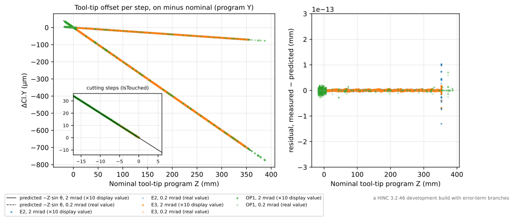
Each step's tool-tip offset in program Y (on minus nominal) against the nominal tip's program Z. Left: one line per value, the steps running from the cutting zone (Z −17 to 0) up to the tool-change heights (Z +353 on E2 and E3, +393.1 on OP1); the inset shows the cutting steps. Right: each step's residual against the prediction, within ±3 × 10⁻¹³ mm. 0.125 mm; a HiNC 3.2.46 development build with error-term branches.
| Clamping | Value | Paired steps | Largest residual | Offset at program zero | Cutting steps' Z | Offset range (program Y) |
|---|---|---|---|---|---|---|
| E2 | 0.2 mrad | 4,535 | 2.02 × 10⁻¹³ mm | 2.75 × 10⁻¹⁴ mm | −8.60…0 | −70.6…+1.78 µm |
| E2 | 2 mrad | 4,535 | 1.92 × 10⁻¹³ mm | 4.25 × 10⁻¹⁴ mm | −8.60…0 | −706.0…+17.80 µm |
| E3 | 0.2 mrad | 5,251 | 1.62 × 10⁻¹³ mm | 1.02 × 10⁻¹⁴ mm | −10.74…0 | −70.6…+2.21 µm |
| E3 | 2 mrad | 5,251 | 2.54 × 10⁻¹³ mm | 8.22 × 10⁻¹⁴ mm | −10.74…0 | −706.0…+22.07 µm |
| OP1 | 0.2 mrad | 313,787 of 313,789 | 2.43 × 10⁻¹³ mm | 8.44 × 10⁻¹⁴ mm | −16.90…0 | −78.6…+3.38 µm |
| OP1 | 2 mrad | 313,787 of 313,788 | 2.23 × 10⁻¹³ mm | 7.64 × 10⁻¹⁴ mm | −16.90…0 | −786.2…+33.80 µm |
- The offset depends on depth alone. 0 at the touch-off height, 3.38 / 33.80 µm toward +Y at the
deepest cut (OP1's Z −16.9), and −70.6…−78.6 / −706…−786 µm at the tool-change height
(
G91 G28 Z0), where the tool is in the air. - The machine coordinates of every step are the nominal run's (ΔMC = 0): the controller computes them on the nominal chain, and the error shows only at the tip.
- The OP1 on runs have one and two more steps, paired by file and line (dilemma 8).
The end faces, milled flat: each face shifts and leans
How it was measured: every vertex of an on run's exported cut was given its signed distance d to the same clamping's nominal cut. Positive = material left (Diff blue), negative = cut too deep (Diff red). Each feature box is a region of the part in the part's own coordinates (the exported mesh's), with z up through the plate's thickness and y along its length.
OP1 from the −Y end, alternating in place between the error terms on (2 mrad, the ×10 display value) and off (the control). The whole end face is cut too deep, more the lower it is (the end bar −20 to −28 µm); the corner block (left) goes from green at its top to red at its bottom. This is the case's on/off comparison picture. Diff colour scale ±0.035 mm (red = cut too deep, blue = material left, green = 0, both signs weighted alike); 0.125 mm; a HiNC 3.2.46 development build with error-term branches.
From the +Y end, the exact opposite: the whole +Y end face keeps material, more the lower it is. Scale, grid and build as above.
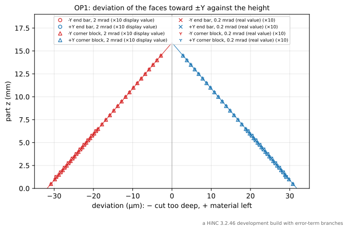
The faces toward −Y (red) and +Y (blue): the median deviation of each 0.5 mm of height against the part's z, for the end bars' end faces (z 1.25–6.55) and the corner blocks' (z 0.5–14.6), the 0.2 mrad values drawn ten times. Every bin lies on the predicted line ∓(15.9027 − z)·sin θ, 0 at the touched-off stock top (z 15.9). 0.125 mm; a HiNC 3.2.46 development build with error-term branches.
| Box | Where (part coordinates) | 0.2 mrad: median (predicted) | 2 mrad: median (predicted) | Ratio |
|---|---|---|---|---|
| F1 | −Y end bar's end face, upper band z 5.0–6.5 | −2.029 (−2.03) | −20.313 (−20.3) | 10.010 |
| F2 | −Y end bar's end face, lower band z 1.3–2.8 | −2.768 (−2.77) | −27.687 (−27.7) | 10.004 |
| F3 | +Y end bar's end face, upper band | +2.029 (+2.03) | +20.298 (+20.3) | 10.002 |
| F4 | +Y end bar's end face, lower band | +2.768 (+2.77) | +27.674 (+27.7) | 9.999 |
| F5 | −Y corner block's end face, top z 11.0–14.6 | −0.629 (−0.62) | −6.310 (−6.2) | 10.025 |
| F6 | −Y corner block's end face, bottom z 0.4–4.0 | −2.731 (−2.74) | −27.311 (−27.4) | 9.999 |
| F7 | +Y corner block's end face, top | +0.629 (+0.62) | +6.298 (+6.2) | 10.007 |
| F8 | +Y corner block's end face, bottom | +2.731 (+2.74) | +27.298 (+27.4) | 9.995 |
Micrometres; d > 0 material left, d < 0 cut too deep. F6 minus F5 is the corner block's end face's own lean, θ per millimetre of height.
The inner faces, the floors and the zero box
From the −Y end, looking slightly down, alternating in place between on (2 mrad, ×10) and off. The near −Y end face is cut too deep; the far +Y end bar's inner face, which faces this way (−Y), is cut too deep as well (F10); the yellow-green of the window floors is the overcut of the tool's tilted bottom. Diff colour scale ±0.035 mm; 0.125 mm; a HiNC 3.2.46 development build with error-term branches.
From the +Y end, looking slightly down: the +Y end face keeps material, and so does the far −Y end bar's inner face, which faces +Y (F9). Scale, grid and build as above.
From above: the floors' overcut comes from the tilted bottom of the tool, about −16 µm of yellow left by the D16 roughing and −5.9 µm on the corner-block tops the D6 finished; the rails' sides toward ±X and their tops stay green. Scale, grid and build as above.
| Box | Where | 0.2 mrad | 2 mrad | Predicted |
|---|---|---|---|---|
| F9 | −Y end bar's inner face, facing the window (y −42) | +2.394 | +23.924 | +2.40 / +24.0 |
| F10 | +Y end bar's inner face (y 42) | −2.394 | −23.937 | −2.40 / −24.0 |
| F11 | rail's outer side facing −X (the zero box) | 0.000 (p01 / p99 ±0.027) | 0.000 (±0.195) | 0 |
| F12 | corner-block top (z 14.903, program Z −1.0) | −0.588 (p01 / p99 −0.599 / −0.547) | −5.873 (−5.985 / −5.473) | −0.59 / −5.9, range −0.60…−0.54 / −6.0…−5.4 |
| F13 | rail top (z 8.603) | −0.563 (−0.598 / −0.382) | −5.618 (−5.968 / −3.819) | range −0.6…0 / −6…0 |
- The inner faces face the window, the other way from the end faces: the −Y end bar's inner face keeps material and the +Y one is cut too deep, each by its height.
- The corner-block top is passed last by the T2 D6 alone, at program Z −1.0 (the D16 goes only to Z −0.85). The D6's bottom is lowest on its −Y side, by R·sin θ = 3 mm·θ: 0.588 / 5.873 µm, almost even over the face. The rail tops are cut by the D6 too, at places that differ in where they lie under the tool, hence a range.
- Faces toward ±X are untouched by this error: the zero box F11 reads a median of 0 at both values.
The holes, drilled on edge: the mouths stay, the holes lean
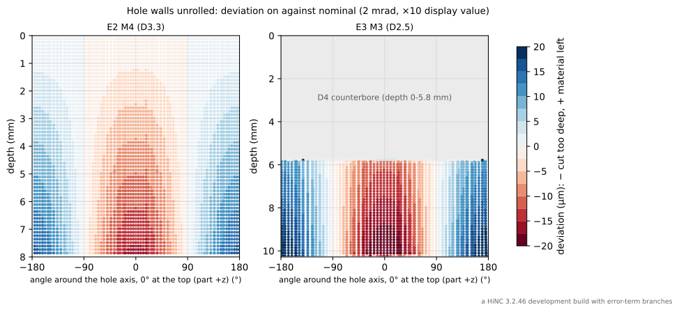
The hole walls unrolled (2 mrad, the ×10 display value): each point is a vertex on the wall of the exported cut, coloured by its signed distance to the nominal cut in 16 steps of 2.5 µm. The top (0°, the part's +z) grows red (cut too deep) with depth and the bottom (±180°) blue (material left); near the mouth almost zero. 0.125 mm; a HiNC 3.2.46 development build with error-term branches.
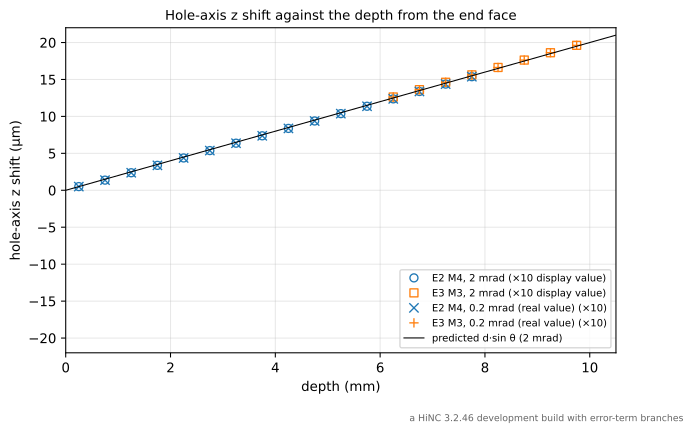
The hole axis's z shift against the depth from the end face: the circle centre of the wall fitted per 0.5 mm slice, on minus nominal, the 0.2 mrad values drawn ten times. Both holes follow d·sin θ, at most 0.13 µm at the end face. 0.125 mm; a HiNC 3.2.46 development build with error-term branches.
| Hole | Value | Slope | Against sin θ | Extrapolated to the end face | Deepest slice (depth) |
|---|---|---|---|---|---|
| E2's M4 (D3.3) | 0.2 mrad | 0.00019945 | 0.997 | −0.010 µm | 1.536 µm (7.75 mm) |
| E2's M4 | 2 mrad | 0.0019945 | 0.997 | −0.095 µm | 15.363 µm (7.75 mm) |
| E3's M3 (D2.5) | 0.2 mrad | 0.00019995 | 1.000 | +0.013 µm | 1.962 µm (9.75 mm) |
| E3's M3 | 2 mrad | 0.0019998 | 1.000 | +0.126 µm | 19.624 µm (9.75 mm) |
The M3 wall starts below the counterbore floor (y 41.2, 5.8 mm deep), so its value at the end face is extrapolated; the M4 starts at the end face. A slope of 0.0019998 is 2.000 µm per millimetre of depth: 2.0 mrad.
| Box | Where | 0.2 mrad: median (predicted) | 2 mrad: median (predicted) | Ratio |
|---|---|---|---|---|
| H1 | E2's M4, top of the deep stretch | −1.102 (−1.06) | −10.996 (−10.6) | 9.976 |
| H2 | E2's M4, bottom of the deep stretch | +1.058 (+1.06) | +10.630 (+10.6) | 10.047 |
| H3 | E2's M4, top at the mouth (the touch-off face) | −0.174 (−0.16) | −1.742 (−1.6) | — |
| H4 / H11 | M2 hole top, deep stretch (x 25.8) | −1.012 (−0.98) | −10.053 (−9.8) | 9.930 |
| H5 / H10 | M2 hole top, deep stretch (x −17.2) | −0.771 (−0.74) | −7.654 (−7.4) | 9.925 |
| H7 | E3's M3, top of the deep stretch | −1.669 (−1.63) | −16.976 (−16.3) | 10.169 |
| H8 | E3's D4 counterbore, top | −0.674 (−0.66) | −6.746 (−6.6) | 10.007 |
| H9a | E3's counterbore floor, above the axis | +0.279 (+0.32), below the noise floor | +2.781 (+3.2) | — |
| H9b | E3's counterbore floor, below the axis | −0.320 (−0.32) | −3.220 (−3.2) | 10.049 |
| H6 | E2's D5.5 seat floor | −0.042, p01 / p99 −0.469 / +0.431 (range ±0.55) | −0.496, −4.707 / +4.292 (±5.5) | — |
- The touch-off face reads zero. The mouth box H3 reads 0.158 times the deep stretch H1 at 2 mrad, and the end face itself is green.
- The floors tilt with the tool's bottom. The counterbore floor keeps material above the axis and is cut too deep below it (H9a, H9b). The D5.5 seat floor is cut by the D4 milling round the seat's axis and by the reamer, both bottoms tilted: its p01 and p99 lie within ±0.55 / ±5.5 µm.
- The two ends mirror each other. E3's two M2 holes (H10, H11) read the same numbers as E2's (H5, H4): the holes at the two ends mirror each other about the plate's mid-plane, and so does the 0.125 mm grid.
- The thin wall above the M4. From the hole to the end bar's top (z 6.803) the wall is 0.850 mm at the mouth and, by the derivation, 0.8484 / 0.834 mm at the exit; this wall was not measured point by point.
E2: the plate on edge in the vise, the −Y end face's hole group seen from above (left, the D5.5 H7 seat; right, the M4 mouth), alternating in place between on (2 mrad, ×10) and off. The end face is green: the touch-off face does not move. The seat floor is blue in its upper half and red in its lower half. The hole walls cannot be seen from above; the two charts above show them. Diff colour scale ±0.005 mm; 0.125 mm; a HiNC 3.2.46 development build with error-term branches.
E3: the +Y end face from above (left, an M2 hole; right, the D4 counterbore with the M3 hole in it), alternating in place between on (2 mrad, ×10) and off. The end face stays green; the counterbore floor's ring is blue above and red below (H9a +2.8, H9b −3.2 µm). Scale, grid and build as above.
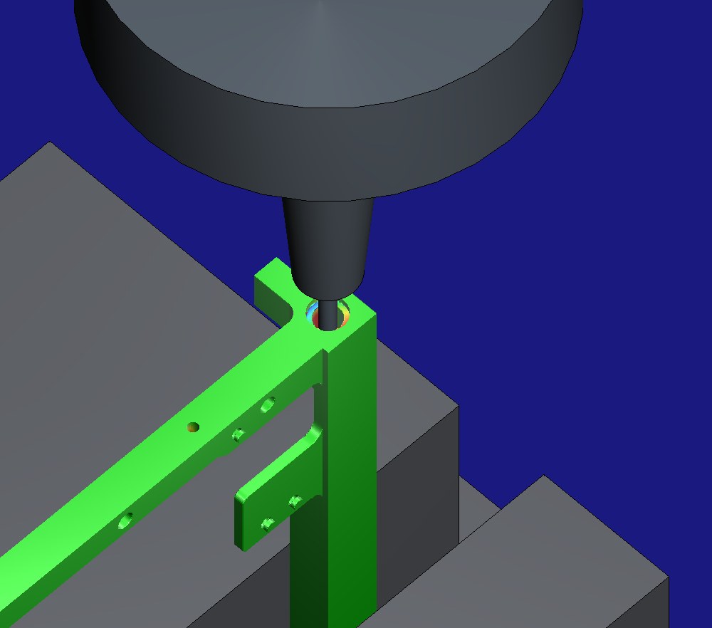
The stock the E3 run with the error terms on recorded (2 mrad, ×10), put back on the canvas, and the
pose program pose-e3-t14.nc played on it: the T14 D2.5 drill goes down the M3 hole's axis to program
Z −6, the nose of its SF4 shrink-fit holder above the end face, and cuts nothing new. Diff colour scale
±0.005 mm; 0.125 mm; a HiNC 3.2.46 development build with error-term branches.
The real value and the display value: the same picture at a tenth of the scale
OP1 from the −Y end, alternating in place between the real value, 0.2 mrad (colour scale ±0.0035 mm), and the display value, 2 mrad (±0.035 mm): the two look the same. So do the E2 and E3 pairs (±0.0005 / ±0.005 mm). 0.125 mm; a HiNC 3.2.46 development build with error-term branches.
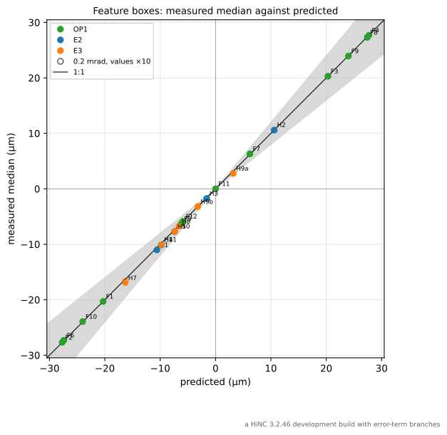
Each feature box's measured median against its prediction (filled: 2 mrad; hollow: the 0.2 mrad value times 10), the grey band ±20 %. Signed distance of the exported cut to the nominal cut; 0.125 mm; a HiNC 3.2.46 development build with error-term branches.
In the 20 boxes that read at both values, 2 mrad reads 9.925–10.169 times 0.2 mrad. Only H9a reads 0.28 µm at 0.2 mrad, below three times its noise floor (0.3 µm), and is reported as the plan says: below the noise floor, 2.781 µm at 2 mrad divided by 10.
The control and the unmarked run
- The control (error terms off, a Diff made again): on E2, E3 and OP1 its tool tip and machine coordinates equal the nominal run's at every step, and its cut deviates by about 10⁻¹⁰ mm, so every box's noise floor takes the plan's floor of 0.1 µm. On the canvas it is all green (the second frame of each comparison picture).
- The unmarked run (E2's trimmed set at 2 mrad only): the controller knows the error, and every
step's tool tip and machine coordinates equal the on run's, and so does the cut. A plain three-axis
program (
G54,G43,G81,G83) gets its machine coordinates from the program and its offsets alone, so the error is cut into the part, marked or not (What a mark changes). A real three-axis controller has to take such an error out with its own squareness compensation, which HiNC does not simulate here.
What the runs cost
All runs used private instances of a HiNC 3.2.46 development build with error-term branches on the shared 32-thread server, with physics off and collision detection on. The instance was restarted and the project loaded from its file before every run, so each VmHWM is that run's own peak.
| Play | Steps | Wall time | Peak memory (VmHWM) |
|---|---|---|---|
| T1: E2 at 2 mrad, nominal / on / unmarked / control | 4,535 | 5 / 20 / 25 / 20 s | 1.27 / 2.12 / 2.30 / 2.33 GB |
| T2: OP1 stage 1 at 0.25 mm, nominal / on | 66,199 | 130.1 / 145.1 s | 1.32 / 1.81 GB |
| E2 nominal / control / on / on ×10 | 4,535 | 5 / 20 / 20 / 20 s | 1.23 / 2.08 / 2.21 / 2.23 GB |
| E3 nominal / control / on / on ×10 | 5,251 | 10 / 25 / 30 / 25 s | 1.26 / 2.10 / 2.26 / 2.25 GB |
| OP1 nominal | 313,787 | 665.7 s | 4.13 GB |
| OP1 control | 313,787 | 685.8 s | 5.36 GB |
| OP1 on, 0.2 mrad | 313,789 | 740.8 s | 5.75 GB |
| OP1 on, 2 mrad | 313,788 | 695.7 s | 5.68 GB |
- Wall time runs from the start of the play to the poll that read
Finished, so it includes the export, the Diff and the stock record after the play; the status was polled every 5 s, so an edge run's time is good to 5 s. - In all, the 18 runs reported took 3,288.2 s of server time, the four OP1 runs 2,788.0 s of it. The edge runs of the first round from E1's record, T1 from E1's record and the trial from OP2's, each under a minute, were kept only as the evidence of dilemma 1.
- Memory. An OP1 run with a Diff peaks 1.2–1.6 GB above the nominal run, which exports its cut but makes no Diff and records no stock.
- The pictures replay nothing. The recorded stock goes back on the canvas with its Diff; for the two holder pictures, a pose program is played on top.
What it means
For a machining engineer.
- A Z axis 0.2 mrad out of square with the table, the factory-acceptance limit of a light milling machine, does different things to the same plate in different clampings. Milled flat, every face toward ±Y shifts and leans: the −Y end bar's end face cut 2.0–2.8 µm too deep and the +Y one with as much material left, the end bars' inner faces the other way round, the floors tilted by the tool's bottom. Drilled on edge, the holes lean toward the part's +z by 0.2 µm per millimetre of depth while their mouths stay where they are.
- The touch-off point is the zero. A clamping touched off on the face it drills into keeps that face and its hole mouths in place; the deviation grows with the distance below the touch-off, 15.9 mm of plate in OP1, 8–10 mm of hole in E2 and E3.
- The signature tells the cause: faces toward ±Y leaning together by the same angle, faces toward ±X untouched, holes leaning by a constant slope from a mouth that does not move.
- What it means for this plate, an inference rather than a simulation: a side panel seated on a leaning end face tilts by θ, so its far end, 94 mm away, moves 94 × 0.2 mrad = 18.8 µm, 19 % of the half band of the 1U drawing's 100.0 ± 0.1 mm (CubeSat Design Specification Rev. 14.1, drawing CDS-14-001). On that count alone the error could reach 1.06 mrad, 5.3 times this machine's acceptance limit. Against ISO 2768-f's angular tolerance of ±30′ for a short side of 10–50 mm, 0.2 mrad is 0.69′. It is an order of magnitude below the finishing deflections the base case measured, up to 23.1 µm on the long D6 and 48.5 µm on the D2: on this plate the small cutters' bending deserves the effort before the machine's squareness.
- In HiNC, a constant error measured on a machine can go into that machine's model, and its shape and size on your own part show before the part is cut.
For a teacher or a student.
- How a small angle upstream of Z becomes the tool-tip offset δ = (0, −Z·sin θ, −Z·(1 − cos θ)), and why it depends on depth alone and not on X, Y or the tool.
- Why the same error leans a milled face whole but leaves a hole's mouth in place: what matters is where the touch-off is and which way the face or the hole runs against the Z travel.
- Why a flat-bottomed tool's floor tilts by R·sin θ, and why the corner-block top, cut by one tool at one height, reads an almost even −0.59 µm.
- Pre-registering a prediction, with the criteria written before the first play, and a dated addendum when a change is forced, written before the rerun.
- How a 0.125 mm grid reads offsets of a few tenths of a micrometre, and where the reading needs care: open stretches of the exported mesh, and slices that run past a hole's exit.
For someone weighing the approach.
- Cost. The 18 runs took 3,288.2 s of server time, at most 5.75 GB of memory each; the four OP1 runs, 2,788.0 s.
- Predictions, written before the first play: the per-step tip meets the formula within 2.54 × 10⁻¹³ mm; the end faces' boxes within 0.11 µm of the prediction at 2 mrad, the inner faces' within 0.08 µm; the hole axes' slopes within 0.3 % of sin θ.
- Misses and gaps, as measured: the corner-block top was first predicted from the wrong tool, and the counterbore-floor box first took in the hole walls (both caught by the review before the plan); the first edge round inherited a broken stock record and was played again from another one; the exported meshes stay open on the edge clampings' flat floors; the counterbore floor's upper side reads below the noise floor at the real value.
Honest limits
- One error only, and a constant one. A real machine also has a squareness of Z to X, straightness of its travels, positioning errors and thermal growth. An error term holds only a constant error; errors that vary with position, backlash, servo mismatch and thermal deformation cannot be put in (Machine Geometric Error).
- The size is a published limit, not a measurement. 0.2 mrad is the factory-acceptance limit of one light milling machine's inspection sheet, not the measured squareness of any machine, and not a typical value for a production vertical machining centre; ISO 10791-2's tolerance was not read in its original text and is not cited. With the opposite direction every sign on this page flips.
- The edge parts lack E1's side holes. E2 starts from OP2's record (dilemma 1); HiNC's defect with clampings placed 120° about a diagonal is not fixed.
- Geometry only. Physics was off: no force, deflection or temperature. The error budget above sets the error against the deflections the base case measured in its acceptance.
- Open stretches in the exported meshes. The flat floors of the edge clampings and OP1's stock bottom export open; the boxes keep clear of them, and HiNC's own Diff has a few points there it cannot measure (dilemma 3).
- The touch-off is modelled by where the pivot sits. A real Y touch-off may probe the plate's side a few millimetres below the end face, which would add a constant e·θ (e the probing depth, 0.2 µm per millimetre at 0.2 mrad); the model puts the zero at program zero.
- The error budget is an inference. No assembly was simulated, “a side panel seated on a leaning end face” is an assumption, and the CubeSat specification gives no GD&T for the rails' squareness or parallelism.
What a reader can take to their own case
- Put the error on a branch of its own, directly upstream of the axis it belongs to. Keep the axis' own motion, its values and its role as they were, and read the chain back after the build (Where an Error Term Goes).
- Put a static error's pivot where the tool tip stands at the touch-off, one pivot per touch-off height. The deviation is then zero at the touch-off point, and the nominal work offset is the one a real touch-off would find. Two touch-off heights need two machine files, or a typed work offset (Work offsets on a machine with error terms).
- Read the clamping before the error. The same squareness leans a face cut by the tool's side, tilts a floor cut by its bottom, and leans a hole drilled along the travel while its mouth stays on the touch-off face.
- Write the prediction down before the first play, and date any change. A change forced after the first round goes into a dated section before the rerun, not into the original text.
- Check the tool tip first, against the formula. The per-step tip checks the model to 10⁻¹³ mm here, before any mesh is read.
- Make the same clamping's nominal cut the ideal geometry. Then the Diff shows the error, not the toolpath's own marks.
- When clampings hand the stock on, check what each run reads. A missing stock record lets a run start from the stock box with one message; log every record's size and time before the play.
- Count a box's vertices before doubting a prediction, and count the exported mesh's open edges: a broken stock record shows there first.
- Fit a hole's axis on whole slices only: a slice that runs past the exit pulls the line.
- Play a display value beside the real one when the real one is a few tenths of a micrometre, keep both in the numbers, and check that their ratio is the ratio of the errors.
- On a plain three-axis program a mark changes nothing in the cut: every error in the chain is cut into the part. A run with the mark cleared differs only under RTCP, a tilted plane or CL playback (What a mark changes).
Source and licence
The plate comes from the TU Wien Space Team's published mechanical design, through the STS1 case:
- Source: Tim Munhowen (TU Wien Space Team, Vienna), SpaceTeamSat1 Mechanical Design, Zenodo,
version 1.0, published 2025-05-21, doi:10.5281/zenodo.15482346.
Search terms if the link moves:
SpaceTeamSat1 Mechanical Design,zenodo 15482346,CS_Yminus.STEP. - Licence: CC BY 4.0, as the Zenodo record states. The licence gives the material as is, without warranty.
- Attribution, as the base case gives it: “SpaceTeamSat1 mechanical design by Tim Munhowen, TU Wien Space Team (Zenodo, doi:10.5281/zenodo.15482346), CC BY 4.0. Machining set-up by Tech Coordinate's agent.”
- What the base case changed: the part geometry is used unchanged; the stock, the operations and clampings, the fixtures, the tools and holders, the programs and the machine are the agent's.
The error's size comes from a manufacturer's published document: the Tormach 1100M factory
inspection sheet TD10547 (revision 1023A), items G5a and G6a, at
https://tormach.com/media/asset/t/d/td10547_1100m_cert_inspect_1023a.pdf. Search terms if the link
moves: Tormach 1100M certificate of inspection, TD10547. The value is a limit on that sheet, not a
measurement of any machine; no machine was measured for this page.
The tolerances of the error budget: the CubeSat Design Specification Rev. 14.1 (Cal Poly SLO, February 2022), appendix B, the 1U drawing CDS-14-001, https://www.nasa.gov/wp-content/uploads/2018/01/cubesatdesignspecificationrev14_12022-02-09.pdf; and ISO 2768-f, the general tolerance on the base case's drawings.
What this page adds. One marked error-term branch on the machine, YZsq. Its kind, its
direction, its pivots and its two values are the agent's choices. The plate's design was not changed.
The pictures are HiNC captures, and the charts are drawn from HiNC's per-step results and cut meshes.
Everything is simulated; nothing was cut. Neither the author nor the TU Wien Space Team took part in
this case or endorses it, and neither does Tormach. This site offers no download; fetch the design from
its Zenodo record.
See Also
- SpaceTeamSat1 CubeSat Structure — the base case: the six plates, the 24 clampings, the agent's own CAM and the acceptance, and the edge clampings placed 120° about a diagonal
- Building Virtual Machine Tools: Error terms — where an error term may go, what a mark changes, the Enable Error Terms switch, and work offsets on a machine with error terms
- Kinematic Topology: Error-Term Branches — the nominal chain the controller solves, and which errors it can see
- Machining Issues Outside the Model: Machine Geometric Error — the machine errors the model leaves out
- Geometry Validation — the geometry difference, its detection radius and its colour scale
- Program Zero Alignment — P0, and typing in a measured work offset
- Plunge against Layer Roughing of a Deep Slot on a Z Axis 0.003° Out of Square — the same kind of error on the same skeleton machine, leaning both walls of a 74 mm deep slot
- RPTU Benchmark Part 8 on a Machine with Three Measured Squareness Errors — three measured squareness errors, a squareness of Z to Y among them, read off an ISO 10791-7-style test piece
- Showcase — the other cases, and how a case page reads