V-Grooves on an 11 mm Sphere with the Tool Tip 10 µm below the B Axis: Both Grooves Cut Deeper from 0 at Their Top to 7 µm at Their Ends, and with the Program in Machine Coordinates a Calibrated Controller Cannot Help
Wu, Liu, Cui and Zong published on Mendeley Data (2023) the NC programs of their research on V grooves
cut into a sphere by ultra-precision five-axis milling: five G-code files and a short description, with
no model, no machine, no tool and no measurement. The programs are written in machine coordinates,
X Y Z B C, with no RTCP. One of them, simulation_singular1 (sim1 below, 1,116 lines), cuts two V grooves
into an 11 mm sphere: groove A with T01 (lines 6–560) and groove B with T04 (lines 563–1114). Each groove
climbs from near the equator, at B ≈ 60°, to its top at B ≈ 0, where the tool axis stands vertical, and
comes down to the equator on the other side. The groove top lies at Z 3.631, 4.12 mm from the C axis, not
at the sphere's apex; “the pole” on this page means this pose at B ≈ 0. An AI agent had built the case
from the programs alone: the only machine they make sense on is a generic five-axis machine with a swivel
head B turning about the tool tip and a table C turning about the sphere centre, which the agent read
back from every five-axis block lying 5.4943 mm from the centre.
On a real machine, where the tool tip sits relative to the B axis depends on tool setting, and it is
always off a little. On this page the agent puts a common setting error into that machine: the tool tip
10 µm below the B axis' centre, as if the tool were 10 µm longer than the program assumes, or the
spindle nose sat 10 µm low in the B head. It is one marked
error term, a translation named TipOffB downstream of B
and directly upstream of the spindle branch. Not one line of sim1 was changed. Six plays ran at
0.0625 mm, three on a trimmed copy of sim1 (its lines 1–288 and the first half of line 289) and three on
the whole program:
- Error terms off: the nominal run. Its cut is the ideal geometry of every geometry difference (Diff) that follows.
- Error terms off again, with a Diff: the control run, for the noise floor.
- Error terms on, the error marked: the controller does not know the error.
- Error terms on, the mark cleared (trimmed copy only): the controller knows the error.
The two runs with the error on typed in the work offset a touch-off at B 0 would find on the real machine: G54 Z +0.010. What came out:
- The tool tip. With the controller unaware of the error, all 4,961 cutting steps of the whole program put the tip's offset on ΔCl = dz·(−sin B·cos C, −sin B·sin C, 1 − cos B), with dz = 10 µm, within 1.8 × 10⁻¹⁴ mm. It is 0 at B = 0 and 9.996 µm once B has turned to 60°. The offset depends on B alone, with C setting its direction, and not on where the tool is on the sphere.
- The groove depth goes by height alone. The tool axis stands at a constant 48.6° to the sphere's normal, so the deviation in the groove's depth is a straight line in the tip's height, Δr = −dz·(3.631 − Z)/5.4943: 0 at the groove top (Z 3.631, B ≈ 0), deeper toward the equator. On the cut mesh the groove floor's medians read −6.45 µm at the groove ends, −4.88 at B ≈ 50°, −3.20 at 40°, −1.79 at 30°, −0.82 at 20°, −0.21 at 10° and −0.03 µm at the top; the prediction from the cutter moved rigidly by ΔCl, computed vertex by vertex, lies within 0.1 µm of each. The groove's deepest point (the on run's smallest radius minus the nominal's) reads −7.33 µm at the ends, against −7.0 µm predicted. The 7 µm cut too deep at the groove ends is 28 % of the program's 25 µm nominal depth of cut.
- What does not move. The two pits the program's own singular blocks cut at the pole lie 3.63084 and 4.52138 mm from the sphere centre, with the error on and off alike, as in the base case. 99.9 % of the pits' vertices lie within 0.5 µm, as do 99.999 % of the uncut sphere (leaving out a patch the nominal mesh lacks) and 100 % of the stem and the foot.
- A calibrated controller cannot help. With the mark cleared, the machine coordinates of the 3,037 paired steps equal the marked run's bit for bit, the tips agree within 1.8 × 10⁻¹⁵ mm, and the file of the cut's vertex distances is the same byte for byte. The program is in machine coordinates, so the controller never solves the kinematic chain: knowing the error, it has nothing to correct. The only difference is one step fewer on line 16, a C positioning in the air (2,806 against 2,807), so that line cannot be compared step by step, and the plan's criterion 4, “step for step the same”, fails as written. The correction can only go into the post-processor, X′ = X + dz·sin B and Z′ = Z − dz·(1 − cos B) in every block, or into putting the tip back on the B axis.
- The control. All 235,904 vertices lie within 0.5 µm, at most 5.0 × 10⁻¹⁰ mm; its per-step series equal the nominal run's bit for bit.
- The cost, on a shared 32-thread server: 16,018–16,019 steps, 20.6–21.0 minutes and a peak memory (VmHWM) of 3.45–3.67 GB per run of the whole program; 5,843–5,844 steps, 10.0–12.0 minutes and 2.70–2.98 GB per trimmed run.
Everything here is simulated; no part was cut.
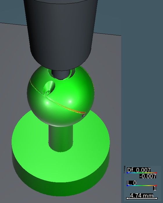
The stock the on run (error terms on, marked) recorded, put back on the canvas with its Diff, and the trimmed program — sim1's lines 1–288 and the first half of line 289 — played on it to park the 60° V cutter (Ø0.1 flat tip, Ø3 shank) upright at the bottom of the pit at B ≈ 0 (B 0.12°, where the tip is off by only 0.02 µm); the Ø3 shrink-fit holder, at 10 mm stick-out, stands above it. The groove in view is groove B: green at its top, past the second pit (the teardrop-shaped pit on the left), turning yellow and red toward its end at the lower right; the pits are green. The small grey spot with a blue and red rim just below that end sits where the exported nominal cut has no faces (dilemma 7): the ideal geometry has no surface there, so HiNC's Diff reads no proper value; it is not a cutting deviation. Diff colour scale ±0.007 mm (red = cut too deep, blue = material left, green = 0, both signs weighted alike); 0.0625 mm; a HiNC 3.2.46 development build with error-term branches.
| The grooves at 0.0625 mm on a HiNC 3.2.46 development build with error-term branches | Predicted before the first play | Measured |
|---|---|---|
| Tip minus nominal tip minus ΔCl, the 4,961 cutting steps of the on run | 0 (the plan allowed 1 × 10⁻⁹ mm) | at most 1.8 × 10⁻¹⁴ mm |
| Largest tip offset |ΔCl| | 2dz·sin(B/2), 9.996 µm at B 59.974° | 9.996 µm |
| Tip offset at B = 0 once the typed G54 is in effect | 0 | at most 1.5 × 10⁻¹⁴ mm (856 steps) |
| Machine X, Y, B and C, on against nominal | the same | the same at all 15,993 paired steps; Z +0.010 mm, the typed G54 |
| Groove ends: deepest point / floor median | Δr = −7.0 µm | −7.33 / −6.45 µm (the floor reads 0.97 Δr, a reading found after the runs) |
| Floor medians at B ≈ 50 / 40 / 30 / 20 / 10° | Δr = −5.05 / −3.31 / −1.89 / −0.86 / −0.22 µm | −4.88 / −3.20 / −1.79 / −0.82 / −0.21 µm |
| Groove top, B < 5° | 0 | −0.03 µm |
| The 31 floor bins (0.125 mm of tip height each) against −dz·(3.631 − Z)/5.4943 | within ±1 µm | −0.005 to +0.29 µm |
| The two pits, closest to the sphere centre | unchanged (the base case: 3.6308 / 4.5214 mm) | 3.63084 / 4.52138 mm, on and nominal alike |
| Pits / uncut sphere / stem and foot | 0 | 99.91 / 99.999 / 100 % of their vertices within 0.5 µm |
| Unmarked against marked (trimmed): machine coordinates and the cut | the same, bit for bit | the same at 3,037 paired steps, the cut's distances byte for byte; line 16 one step fewer |
| Control against nominal | 0 | every step bit for bit; every vertex within 5.0 × 10⁻¹⁰ mm |
| Server time of the six plays / peak memory of a whole-program run | — | 5,711.3 s / 3.45–3.67 GB |
The case
The data set (source and licence below) holds five G-code files and the record's short description. It names no machine beyond “the five-axis machine tool”, and states no tool, stock, material or measurement; the companion article in Precision Engineering is not open access and was not read. An AI agent built the data set into a HiNC project, the Mendeley sphere V-groove case. It read the machine chain back from the programs by three checks — a constant distance, a constant tool angle and plane curves —, chose the stock, the cutter and the holder, played the authors' programs without and with their singularity algorithm, and reproduced the pits that the singular blocks at the pole drag the tool tip into. That case has no page of its own here; the facts this page takes from it are given below. Its machine has the tool tip exactly on the B axis: the program is right only under that assumption, and the agent read the machine back from it. This page asks what happens when the tip is off. On a real machine the tip's position comes from tool setting and is always off a little; at 10 µm, what do the two grooves look like, and does it matter whether the controller knows? What the agent was given:
- The base case's project and programs.
- sim1. The data set's programs are ISO G-code in machine coordinates: every motion is
G01, with no RTCP and noG43. Each pass starts withG01 X15 Y0 F2,B0 F5,C0 F50andZ0 F2, moves axis by axis to its start (X, Z, Y, then B ≈ 60 and C), feeds in along X by 1 mm at F0.618, runs its five-axis blocksX Y Z B C F20, and retracts to X15. In sim1, groove A's five-axis blocks run on lines 21–557, with the singular block at the pole on line 289 (C turns 179.88° within oneG01); line 562 isT04 M06; groove B's run on lines 577–1113 and pass near the pole on lines 843–845 (as read from the NC by the designer agent, the agent that drafted this study). - The machine, derived by the base case and built for it, with no maker's geometry: table C turns
about −Z through program zero, the sphere centre; head B turns about +Y through the tool tip; machine
zero is the programs' park point X15 Y0 Z0 B0 C0, and G54 is (−15, 0, 0). The chain runs
O→base→Y→X→C→won the table side andbase→Z→B→S→ton the tool side. The tool mountS→tsits at (15, 0, 103) in the B anchor's frame and the tool is 70 mm long, so the tip is at (15, 0, 33), exactly B's pivot. Of 54 readings of B and C, this is the only one that makes every pass a plane curve, with different grooves on different planes. - Stock, tool and holder, chosen by the base case: a sphere of R 5.5193 (25 µm above the program's
radius, 5.4943) on a Ø4 stem and a Ø16 × 4 foot, on a 50 × 50 × 15 plate as the fixture; a 60° V
cutter with a Ø0.1 flat tip (
TaperAptD0.1, β 30°, flute height 2.511) and a Ø3 shank 40 mm long, in a Ø3 shrink-fit chuck at 10 mm stick-out; T01 and T04 are the same cutter. The tip, the centre of the flat end, runs on the program's sphere 25 µm below the stock; the flat end's rim reaches 37.5 µm deeper, so the groove's deepest line lies 62.5 µm below the stock surface. - The base case's result. Played the way a controller that interpolates the machine axes plays it, sim1's singular blocks drag the tip into the sphere: the cut comes to 3.6308 mm from the centre at line 289, and sim2 played alone, whose lines 288–289 are sim1's 844–845, to 4.5214 mm.
- sim1. The data set's programs are ISO G-code in machine coordinates: every motion is
- HiNC's error terms. An axis or the spindle of the machine chain can be given an error term, a static branch of its own just before the axis's branch: it carries
a measured error rather than part of the design. The controller,
XyzabcSolver, which turns NC into machine coordinates, always solves on the nominal chain, taking the marked branches as absent. While the project's Enable Error Terms switch is on, the simulated machine keeps the marked branches as it moves, cuts and checks collisions. So the error is cut into the part, as on a real machine whose controller does not know it. Without RTCP, a tilted plane or CL playback, every error in the chain is cut into the part, marked or not (Error-Term Branches). - Touch-off and P0. HiNC's P0 measures program zero on the nominal chain. On a real machine, the work offset found by touching off already holds the constant shift the error causes at the touch-off pose. To reproduce a given shop's result, the manual says to type in the work offset that shop measured (work offsets on a machine with error terms).
- A placement rule. HiNC's product owner ruled on 2026-10-06 that an error term goes only directly
upstream of a role branch, an axis X … C or the spindle, on a new anchor of its own named after that
branch with
errafter it. - The request. HiNC's product owner asked for error-term showcases built on earlier cases, product cases and paper cases alike, with the heavy runs on a shared server.
What nothing states:
- Which constant error leaves a mark on this sphere. This batch's default for a rotary axis, a translation directly upstream of it, leaves 0 on the part with this machine and this program (dilemma 2).
- That the spindle branch binds no role. The machine file's
spindlebranch (B→S) is a No Transform and binds no Spindle role, while the ruling puts an error only directly upstream of a role branch (dilemma 1). - The G54 Z a touch-off would find. It has to be derived from the machine chain.
- Whether a 0.0625 mm grid reads 10 µm. The V groove itself is smaller than a cell (25 µm deep at the tip, 62.5 µm at its deepest line), and the 7 µm at the groove ends is 11 % of the cell width (dilemma 3).
- That the tip does not depend on the spindle angle. The spindle rotation the agent adds must turn about an axis through the tip, or the spindle angle would change the cut (dilemma 1).
What is new here:
- An error on the tool side of a swivel head. It is the spindle's error term, between B and the spindle branch: the place the manual gives a spindle housing's tilt on a B head (where an error term may go); here it holds a translation along the tool axis.
- A five-axis program in machine coordinates. The five-axis error-term cases before this one, the
wheel, the BCAM blade and the NIST frustum, play under RTCP (
G43.4orM128), where a controller that knows the error cuts the nominal part. Here the controller never solves the chain, so knowing the error changes nothing, and the correction belongs in the post-processor. - Two fingerprints on one part. The program's own error, the pits at B ≈ 0, and the machine's error, a groove depth growing with B, are told apart on one sphere.
- A depth error by height alone. The tool stands at a constant 48.6° to the sphere's normal, so the deviation in the groove's depth depends only on the height of the point.
What the agent built
Each value is marked read (from the base case or a document), derived (computed from what was read) or chosen (the agent's decision). dz is how far the B axis' centre stands above the tool tip, 10 µm.
| Value | Source | |
|---|---|---|
| Meaning | The B axis' centre of rotation stands 10 µm above the tool tip: the tool is effectively 10 µm longer than the 70 mm the program assumes, or the spindle nose sits 10 µm low in the B head. A location error of the B axis relative to the spindle, along the tool axis | chosen: the kind of error and its sign |
| Size | 0.010 mm, in the B anchor's frame, along −Z (the tool axis at B = 0) | chosen: a typical value, at the low end of the usual range for the location error of a rotary axis; this generic machine has no measurement, and the companion article, which is not open access, was not read |
| Prerequisite | spindle (B→S) changed from No Transform to the spindle's Dynamic Rotation: axis (0, 0, −1), pivot (15, 0, 103), the tool mount's axis, which passes through the tool tip as the B axis does; bound to the Spindle role |
chosen: the ruling needs a spindle role to put the error in front of; with the pivot through the tip, the spindle angle does not move the tip |
| Where | Directly upstream of the spindle branch. A new anchor spindleerr splits the old B→S: B→spindleerr is named TipOffB and carries a Static Translation (0, 0, −0.010), marked as an error term; the spindle's Dynamic Rotation moved whole onto spindleerr→S, and the Spindle role was bound to it again, its values unchanged |
chosen: following the owner's ruling |
| The chain | Table side O→base→Y→X→C→w, tool side base→Z→B→spindleerr→S→t |
read: the topology read back after the build |
| Work offset | The two runs with the error on, marked and unmarked, typed in G54 = (−15, 0, +0.010), the value a touch-off at B 0 would find; the nominal and control runs keep the case's (−15, 0, 0) | derived: at B 0 the tip stands 10 µm low, and a touch-off takes that into G54 Z |
Why the tool side, and not this batch's default placement for a rotary axis (the designer agent worked out each candidate on this sphere):
- A translation upstream of B carries B's pivot together with the spindle and the tool hanging below it, so the tip stays on the B axis and every B shifts it by the same constant, which a touch-off takes out: 0 on the part. Upstream of C likewise: the sphere hangs below C, and the part shows 0.
- A tilt of the B axis only turns the tool axis; the tip on the axis does not move. The squareness of the linear axes over the ±4 mm they travel here comes to only 0.2 µm.
- The tip off the B axis is the only constant error on this machine that leaves a mark of micrometres on the part — and it is the very assumption this kind of program rests on most.

The machine-tool cluster (GeneralMechanism) in the Topology column of the Equipment page. A new anchor, spindleerr, sits between B and the spindle. TipOffB (a Static Translation, B → spindleerr) is drawn thick with the orange Error term badge; the spindle's Dynamic Rotation now sits on spindleerr → S and is bound to the spindle role (Machine Tool · Spindle). The table side O → base → Y → X → C → w is untouched. A HiNC 3.2.46 development build with error-term branches, English interface.
Where the tip goes: the predictions written before the first play. Points without a mark are the plan's; points marked (design) are written only in the designer agent's design.
- In the B anchor's frame the tip is at (15, 0, 33 − dz). As B turns about the pivot (15, 0, 33), the tip swings about the true B centre: relative to the sphere centre it is off by e = dz·(a0 − a(B)), where a(B) = (sin B, 0, cos B) is the tool axis' direction and a0 = a(0). At B = 0, e = 0 whatever C and X Y Z are, so the touch-off pose has no offset; |e| = 2dz·sin(B/2).
- In program coordinates: ΔCl = Rz(C)·e = dz·(−sin B·cos C, −sin B·sin C, 1 − cos B).
- (design) Machine coordinates: MC.X, MC.Y, MC.B and MC.C the nominal run's; MC.Z higher by dz, which is the typed G54 Z, not the controller's doing.
- The groove's depth. The tool axis stands at a constant γ = 48.634° to the sphere's normal n, so Δr = ΔCl·n = −dz·(cos γ − Z/R) = −dz·(3.6310 − Z)/5.4943, with Z the step's program Z and R = 5.4943. Δr depends only on the point's height on the sphere. The groove top, Z 3.631, is exactly the height at B = 0, so it is 0 there, and it grows deeper toward the equator. Predicted: B ≈ 10° −0.22, 20° −0.86, 30° −1.89, 40° −3.31, 50° −5.05 µm, and −7.0 µm at the four groove ends (B ≈ 59.7°); (design) the four ends one by one (lines 21, 557, 577 and 1113, B 59.6–59.9°) −7.01, −7.03, −6.98 and −7.04 µm.
- Off the groove's plane: the grooves stay in their planes; (design) groove A 0, groove B 0.0007·dz = 0.007 µm.
- Along the groove (design): 0.71·dz = 7.1 µm at the ends, which moves only each groove's start and end.
- The two pits (lines 288–289 and 843–845) do not move; the uncut sphere, the stem and the foot: 0. (design) There B ≤ 0.27° and |ΔCl| ≤ 0.046 µm, so the pit depths of 1.863 and 0.953 mm do not change; the fixture: 0 as well.
- Unmarked. The program is in machine coordinates, MC = program + G54, and the controller never goes through the kinematic chain. With the mark cleared, the machine coordinates, the tip and the cut should therefore be the marked run's bit for bit, not merely close to them, so the unmarked run is played once, on the trimmed copy, as evidence.
The runs:
| Run | Program | Enable Error Terms | TipOffB |
G54 | Diff | Purpose |
|---|---|---|---|---|---|---|
| t-nominal | trimmed copy (289 lines) | off | marked (not in effect) | (−15, 0, 0) | none; exports its cut (449,511 triangles) | trimmed: nominal, the ideal geometry |
| t-unmarked | trimmed copy | on | mark cleared | (−15, 0, +0.010) | yes; exports its cut | trimmed: controller knows the error |
| t-on | trimmed copy | on | marked | (−15, 0, +0.010) | yes; exports its cut | trimmed: controller unaware |
| f-nominal | sim1 (1,116 lines) | off | marked (not in effect) | (−15, 0, 0) | none; exports its cut (454,761 triangles) | the ideal geometry |
| f-control | sim1 | off | marked (not in effect) | (−15, 0, 0) | yes; exports its cut | the noise floor |
| f-on | sim1 | on | marked | (−15, 0, +0.010) | yes; exports its cut | controller unaware; the pictures |
Common to every run:
- A 0.0625 mm grid, with Fixed Pace motion resolution at 0.01 mm and 0.5°, physics off, collision detection on and pause on failure off.
- The Diff (Geometry Validation): the ideal geometry is the cut the nominal run of the same set exported, with a detection radius of 1 mm and a colour scale of ±0.007 mm. So the Diff shows only what the error changes, not the program's own pits and grooves.
- The per-step series record Cl.X/Y/Z (the tip, the centre of the flat end, in program coordinates with the sphere centre as origin), Cl.I/J/K (the tool axis), MC.X/Y/Z/B/C, FileNo, LineNo, IsTouched and ToolId.
How the agent managed the work
- Criteria and predictions first. The plan, its predictions and seven criteria were committed before the first play. The build ran from 21:42:51 to 21:42:58 on 2026-10-06, and the first run started at 21:43:30.
- The build, through the web API only. The agent's tools saved the base project as a new error-term
project, with its
NC/folder and the trimmed program copied, and disabled the base project's record entries. The two prerequisite steps came first, the spindle branch made a Dynamic Rotation and bound to Spindle; thenTipOffBwas inserted and marked. The mission: machining resolution 0.0625 mm, motion resolution Fixed (0.01 mm / 0.5°), collision detection on, pause on failure off, physics off, five program entries (sim1, sim2, exp1, exp2 and the trimmed program, one enabled at a time), an STL export of the cut, and the post-execution entry. - Trimmed runs first. The trimmed program,
pose-sim1-line289-half.nc, is sim1's lines 1–288 unchanged and the first half of line 289: the approach to B 59.97°, groove A's first half from the equator to its top, and the tool parked at the bottom of the pit at B 0.12°. It passes through the approach from B 0 to 60, the climb of groove A, the park at B = 0 and the pit: the smallest case that checks the build, the formula, the touch-off pose and the pit, and decides which value to show. Three runs, nominal (exporting the trimmed ideal geometry), unmarked and on, played one after another on the same private instance, 21:43:30–22:16:22. - The whole program, one run at a time. sim1 whole, nominal (exporting the ideal geometry), control and on, back to back on 2026-10-07 from 01:34:18 to 02:36:57. Before each run the instance was restarted and the project loaded from its file, so each of these runs' peak memory is its own.
- The nominal cut as the ideal geometry. The cut the nominal run exported, 454,761 triangles for the whole program and 449,511 for the trimmed copy, became the ideal geometry, with a detection radius of 1 mm and a colour scale of ±0.007 mm. The Diff then holds only what the error changes, not the program's own pits and grooves. Each run with a Diff recorded its final stock, which the pictures put back on the canvas.
- sim1 as published. The whole-program runs play sim1 from its NC entry, unchanged; the trimmed program is a shortened copy of it.
- Every number from the records. The agent's analysis script computes the numbers on this page from the run records and keeps each with its source. The vertices the distance search read beyond 8 µm were recomputed on the shared server as exact point-to-triangle distances against the nominal cut. A second script, written independently, recomputed the pit depths, the deepest points at the groove ends, the binned medians, the tip residual, the steps at B = 0, the unmarked pairing and the chord of line 16 from the per-step series and the vertex distances, and found the same values.
- Pictures in both interface languages. The Diff pictures put the recorded stock back on the canvas with its Diff, without replaying; the holder pictures put the on run's stock back and play the trimmed program on it, which parks the cutter at the bottom of the pit. The canvas shows no interface text, so the English and Chinese canvas captures are the same pixel for pixel.
- Where a person stepped in. HiNC's product owner asked for error-term showcases built on earlier cases, product cases and paper cases alike, with the heavy runs on a shared server, and ruled where an error term may go. The error, its size and sign, the spindle prerequisite, the touch-off value, the predictions and the criteria are the agents' own: the designer agent worked them out, and the agent that ran the case wrote them into the plan.
The criteria as committed before the first play:
| # | Criterion |
|---|---|
| 1 | Build: spindle is a Dynamic Rotation bound to Spindle; TipOffB is a marked Static Translation (0, 0, −0.010) on B→spindleerr; the roles check is empty; the case's files outside the error-term folder are unchanged |
| 2 | Every run: Finished, every program line executed, no collision; only the expected Diff--TargetNotClosed added |
| 3 | On: on every cutting step, |Cl − Cl nominal − ΔCl| ≤ 1 × 10⁻⁹ mm (paired by step index when the step counts agree, otherwise by machine coordinates); at the touch-off pose (B = 0), the steps' offset ≤ 1 × 10⁻⁹ mm |
| 4 | Unmarked (trimmed): Cl the same as the on run's, step for step |
| 5 | Control: by vertex distance, at least 99 % of the vertices with |deviation| ≤ 0.5 µm; the nominal cut's two pits as deep as the case's accepted value (3.6308 mm from the sphere centre) |
| 6 | The grooves, on against nominal, by vertex distance: the floor's vertices binned by Z, the median = −dz·(3.631 − Z)/5.4943 ± 1 µm; −7.0 ± 1.5 µm at the groove ends |
| 7 | Cost: wall time and VmHWM recorded for every run |
The dilemmas
Each one is told as its situation, the risk if it had been missed, how it was noticed, the resolution, and the evidence that the resolution held.
1. The spindle branch binds no role
- Situation. The machine file's
spindlebranch (B→S) is a No Transform and the file has no spindle element, so the Spindle role is not bound: by the manual, a spindle branch on No Transform is no spindle (names a machine file is read by). The owner's ruling puts an error term only directly upstream of a role branch. - Risk. With
spindlebound to no role, an error put in front of it would not follow the ruling. And in adding the spindle role, a rotation whose axis missed the tip would let the spindle angle move the tip, and the cut would no longer be the base case's. - How noticed. The designer agent read the machine file and the manual's rule that the spindle is found by its place.
- Resolution. Two prerequisite steps:
spindlemade a Dynamic Rotation, axis (0, 0, −1), pivot (15, 0, 103) — the tool mount's axis, which passes through the tool tip as the B axis does — and bound to Spindle; thenTipOffBinserted, with the spindle's rotation moved ontospindleerr→Sand its role bound again. - Evidence. The moved values are the same as before the move, and the roles check was empty before and after. The nominal cut's two pits lie 3.63084 and 4.52138 mm from the centre, as in the base case without the prerequisite: 3.6308 mm is sim1's accepted value, and 4.5214 mm the closest point of sim2 played alone, whose lines 288–289 are sim1's 844–845. That the control run equals the nominal run bit for bit shows only that the two runs repeat, as both carry the prerequisite.
2. This batch's default placement for a rotary axis leaves nothing on this machine
- Situation. This batch's default for a rotary axis' location is a translation directly upstream of the axis. The program is in machine coordinates without RTCP. A translation upstream of B carries B's pivot along with the spindle and the tool below it, so the tip stays on the B axis, and every B shifts it by the same constant; upstream of C likewise, as the sphere hangs below C. A touch-off takes the constant out, and the part shows 0.
- Risk. Done by default, six runs would end with an all-green part and a page with nothing to say.
- How noticed. The designer agent worked every candidate out on this sphere: upstream of B, upstream of C, a tilt of the B axis, the squareness of the linear axes.
- Resolution. The one that leaves a mark, the tip off the B axis: a translation downstream of B and
upstream of the spindle, on an anchor named
spindleerr. A touch-off at B 0 takes the 10 µm into G54 Z, so the two runs with the error on typed in (−15, 0, +0.010). - Evidence. That the default placement leaves 0 on the part is the designer agent's derivation; it was not played. The typed G54 is right: the 856 steps at B = 0 with it in effect lie within 1.5 × 10⁻¹⁴ mm of the nominal run's. The groove ends read −6.45 µm on the floor and −7.33 µm at the deepest point, clearly.
3. Can a 0.0625 mm grid read a real 10 µm?
- Situation. The V groove itself is smaller than a cell, and the 7 µm at its ends is 11 % of the cell width. The design kept a ×50 fallback — dz 0.5 mm, G54 Z +0.5, −0.352 mm at the groove ends, a colour scale of 0.35 mm — for the trimmed runs to decide on.
- Risk. With a magnified value, every picture needs a conversion and the whole program one more run; with the real value, the error might read as noise.
- How noticed. The design wrote the rule down beforehand: keep the real value if, in the trimmed runs, the groove-end window of the on run reads at least 5 µm deeper than nominal and the control's 99th percentile is at most 2 µm.
- Resolution. The trimmed set had no control run, so only the rule's first half could be measured when the choice was made: the floor median of groove A's start window read −6.47 µm, deeper than 5 µm. The whole program ran with the real 10 µm and a ±0.007 mm colour scale, and the ×50 run was not played.
- Evidence. Measured afterwards, the whole program's control has a 99th percentile of 4.2 × 10⁻¹⁰ mm, so the rule's second half, measured only after the choice, holds too; the 31 floor medians lie within 0.29 µm of the formula; the Diff pictures turn from green to red along the grooves.
4. The on run has one step more, and zero offset at B = 0 holds only once the typed G54 is in effect
- Situation. Criterion 3 says to pair the runs by step index when the step counts agree, otherwise by
machine coordinates. The on run has 16,019 steps and the nominal 16,018, and wherever G54 is in effect
the typed G54 Z puts the on run's MC.Z 10 µm higher. The extra step comes from the
Z0of lines 9 and 565: with G54 Z +0.010 each of them moves 10 µm, where the nominal run's do not move, and line 562's tool change, raising Z back to machine zero, takes one step fewer in the on run (24 against 25). - Risk. Paired by step index, every step from line 9 on would be misaligned; paired by machine coordinates as written, the steps whose Z differs by the typed 10 µm would find no partner. They would pair once that 10 µm is taken off, but that was not done.
- How noticed. Grouping the two runs' steps by
LineNo, line by line. - Resolution. The runs are paired by program line, step by step wherever a line has the same number of steps in both; the three lines whose counts differ (9, 562 and 565, 26 steps in the air) stay unpaired. The steps at B = 0 fall into two groups. The 856 with the typed G54 in effect have no offset. The 909 at the start pose and after the T04 tool change, before a Z word is given (lines 2, 563 and 564), keep Z at machine zero in both runs, and there the tip stands exactly 10 µm low: the pose before the touch-off takes effect, not a fault of the error model. The on run also has two cutting steps more, the last steps of the X approach on lines 20 and 576, where the tip, about 7 µm further toward the sphere centre, just reaches the stock.
- Evidence. All 4,961 cutting steps lie within 1.8 × 10⁻¹⁴ mm of the prediction. The design's other reading, |Cl − Rz(C)·(MC − the on run's G54)|, is 0 on those 909 steps too. In the trimmed runs only the start step of line 2 differs by 10 µm.
5. The unmarked run has one step fewer: line 16 follows the controller's own tip chord
- Situation. Criterion 4 asks the unmarked run's tip to equal the on run's, step for step. The unmarked run has 5,843 steps and the on run 5,844; the difference is line 16, the C0 → C144.756 positioning in the air (2,806 steps against 2,807). Every other line has the same count.
- Risk. Failing it as written and stopping there, or taking it for the controller really compensating something.
- How noticed. Comparing the step counts line by line.
- Resolution. A line is cut into the larger of “tip chord / 0.01 mm” and “rotation / 0.5°” steps, and the tip here is the controller's own. Marked, the controller solves on the nominal chain: the tip stands 14.7247 mm from the C axis, the chord is 28.0674 mm, and the line takes 2,807 steps. Unmarked, it solves with the error: 14.7162 mm, 28.0514 mm, 2,806 steps. Both counts match. This is a consistency read off the numbers, not traced in the code. Every cutting line has the same count, with the machine coordinates bit for bit the same. Criterion 4 is recorded as written, failed; the cut is the same.
- Evidence. The 3,037 paired steps have bit-identical machine coordinates, and the cut's vertex distances are the same byte for byte.
6. What the groove floor, the steep wall and the deepest point each read of Δr
- Situation. Criterion 6 says: the floor's vertices binned by Z, the median = Δr ± 1 µm. A groove's section has two faces. The cutter's 30° cone side cuts a gentle face, only 11.4° off the sphere; its flat end cuts a steep wall, whose normal is the tool axis, 48.6° off the sphere's normal. The two meet at the flat end's rim. The vertex distance measures each face's displacement along its own normal.
- Risk. The steep wall reads only 0.71 Δr; read without telling the faces apart, it would look like a fault of the error model. (With the wall's vertices merged into the floor, criterion 6 still passes: the 31 bins' medians lie within 0.44 µm of the formula, the deepest four bins read 0.94–0.95 Δr, and the four groove-end windows −6.41 µm.)
- How noticed. Once binned, the groove's vertices fell into two groups. With the nominal cutter moved rigidly by each step's ΔCl and the face's normal taken vertex by vertex, each group matched.
- Resolution. Vertices within 12 µm of the cutter's cone or of its flat end are sorted into floor and wall (a rule the analysis set itself), and criterion 6 is judged on the floor. The wall is compared with the prediction along its own normal, −dz·(1 − cos B), and the deepest point (the on run's smallest radius minus the nominal's) reads Δr directly.
- Evidence. Measured minus the vertex-by-vertex prediction has a median of +0.02 µm on the floor and +0.01 µm on the wall (the windows' wall medians within 0.19 µm of their prediction, the 0.125 mm bins within 0.50 µm). The deepest point at the groove ends reads −7.33 µm (design −7.0). With one vertex per bin, the deepest point scatters by ±0.9 µm, while the floor medians stay within 0.3 µm.
7. The exported nominal cut lacks a patch of faces below the end of groove B, and HiNC's own Diff has more NaN leaves in the on run
- Situation. The on run's vertex distances run from −253 µm to +130 µm, twenty-odd times the largest tip offset of 10 µm.
- Risk. Read as the error, they would say the sphere was spoiled; set aside as artefacts of the measurement, they would hide a defect of the reference mesh itself.
- How noticed. A first screen: a cut whose cutter moved rigidly by at most 10.00 µm cannot lie more than 10.5 µm from the nominal cut — true for exact faces, not where a mesh samples a sharp edge differently — and 222 vertices lie beyond that. The 243 vertices the search read beyond 8 µm were then recomputed on the shared server as exact point-to-triangle distances against the nominal cut: all 243 are real distances (none an artefact of the search), the exact values within 1.5 × 10⁻⁸ mm of the search values.
- Resolution.
- A patch of faces missing in the reference. 213 of them lie on a patch of uncut sphere below the end of groove B (lines 1097–1114, B 56.6–59.9°), all on the stock sphere (radius 5.5181–5.5192 mm), 8.1–253.3 µm from the nominal mesh's nearest triangle. The control run's exported mesh has no vertices there either: for 198 of the on run's vertices no control vertex lies within 0.05 mm, while elsewhere on the uncut sphere every on-run vertex has a control vertex within 5.2 µm, and every control vertex lies within 5.0 × 10⁻¹⁰ mm of the nominal mesh. So the exported nominal (and control) cut lacks a patch of faces there: it is not a difference of the cut, and not an artefact of the search. Why it is missing, the records do not tell; the exported STL stayed on the server and was not looked at directly. The analysis leaves that patch out of the region statistics: the vertices beyond 20 µm widened by 0.05 mm, a box of 0.65 × 0.82 × 0.98 mm, the vertices in it at the uncut radius — 327 of the on run's, 116 of the control's.
- The grooves' sharp bottom edges. Another 30 lie on the bottom edges of the two grooves (10 in groove A, 20 in groove B, −19.4 to −8.1 µm), and the exact distances confirm them as real mesh differences too: the 0.0625 mm mesh rounds the sharp edge differently in the two cuts. The 10 of them beyond 10.5 µm, all in groove B, fall outside the screen above and are left out of the region statistics; the screen does not hold on a mesh's sharp edge, so they are not misreadings, only not counted there.
- HiNC's own Diff reports 72 NaN leaves and 732 unmeasured wires in the on run, against 1 and 323 in the control, and the records give no positions. In the holder picture, the small grey spot with a blue and red rim right below the end of groove B sits, by eye, in this patch, and may be those (not verified).
- Evidence. The exact distances of the 243 vertices; the control's mesh, with no vertex beyond 5.0 × 10⁻¹⁰ mm.
8. The Fixed Pace hull did not degenerate
- Situation. A Fixed Pace step removes the convex hull of the cutter at its two poses, and that hull degenerates when the cutter turns about a point of itself that does not move — as on this machine, where every B move turns the cutter about its own tip. The base case's cutter has a 0.1 mm flat tip for that reason: with a pointed cone and with a round tip, the base case's runs did not get through these B moves. With the error on, the cutter turns about a point 10 µm off its tip, a new input.
- Risk. The on run stopping or stalling at the approach's B 0 → 59.97 (line 15), or at line 571's B 0 → 59.82.
- How noticed. The design listed it as a doubt; the trimmed runs' approach meets it first.
- Resolution. Run, and watch.
- Evidence. All six runs ended
Finished, and the on and nominal runs took comparable times: 1,236 against 1,251 s for the whole program, 601 against 721 s trimmed.
Results and benefits
Measured on a HiNC 3.2.46 development build with error-term branches, at 0.0625 mm with physics off. “Measured” here means measured on HiNC's simulated results.
Five of the seven criteria passed in full (1, 2, 5, 6 and 7). Criterion 3 passed on the cutting steps and failed as written at the touch-off pose, on 909 steps in the air before the typed G54 Z took effect (dilemma 4); criterion 4 failed as written on one positioning line in the air (dilemma 5).
| # | Verdict | Measured |
|---|---|---|
| 1 | met | spindle on spindleerr→S: a Dynamic Rotation, axis (0, 0, −1), pivot (15, 0, 103), role Spindle, its values unchanged by the move onto spindleerr. TipOffB on B→spindleerr: a Static Translation (0, 0, −0.01), marked as an error term. The roles check was empty before the prerequisite, after it and after the error was added, and empty again as each of the six runs read it back. The base project loaded, and its copy saved and reloaded, with no message; the messages of each run's reload of the project with the error were not kept in the records. After the build and the six runs, git found no change to the case's files outside the error-term folder in the working copy the runs used |
| 2 | met | All six runs Finished. Messages at warning level and above: nc holds only Parsing--Unconsumed, for the base case's own G14 and M25 (two in the whole program; one in the trimmed program, which has no M25); shell holds one Diff--TargetNotClosed in each of the four runs with a Diff, as the ideal geometry is an exported open mesh; step and ncManip are empty, so there is no Collision--Detected and no stroke-limit message. Every program line that moves an axis has steps: 1,094 lines in the whole program, the last with steps line 1114, X15 F2 (in the nominal and control runs, line 565, Z0, does not move: T04's tool change has already raised Z to machine zero, which is their program Z0); 276 lines in the trimmed program, up to line 289 |
| 3 | met on the cutting steps; at the touch-off pose (B = 0), as written: failed | The on run has one step more than the nominal (16,019 against 16,018), and the typed G54 Z puts MC.Z 10 µm apart wherever G54 is in effect, so the runs were not paired as the plan says but by program line (dilemma 4): 15,993 steps paired, leaving 26 steps in the air on lines 9, 562 and 565. All 4,961 cutting steps (the nominal has 4,959, the on run 2 more) are paired, with residuals within 1.8 × 10⁻¹⁴ mm; the trimmed runs' 1,494 cutting steps also within 1.8 × 10⁻¹⁴ mm. Of the 1,765 paired steps at B = 0, the 856 with the typed G54 Z in effect lie within 1.5 × 10⁻¹⁴ mm; the other 909, on lines 2, 563 and 564 (the start pose, and after the T04 tool change before a Z word is given, with Z at machine zero in both runs), lie exactly 10.000 µm apart, all in the air. The design's other reading, |Cl − Rz(C)·(MC − the on run's G54)|, is 0 on these steps too |
| 4 | as written: failed | The unmarked run has 5,843 steps and the on run 5,844; the difference is line 16, a C0 → C144.756 positioning in the air (2,806 against 2,807 steps, with the same end points; dilemma 5), so line 16 cannot be compared step by step. The other 3,037 paired steps have bit-identical MC.X/Y/Z/B/C, Cl within 1.8 × 10⁻¹⁵ mm and the tool axis within 2.3 × 10⁻¹⁶; the file of the cut's vertex distances is the same byte for byte, and so are the eight numbers of Diff--Stats |
| 5 | met | The control's 235,904 vertices all lie within 0.5 µm (the largest |d| 5.0 × 10⁻¹⁰ mm), and its per-step series equal the nominal's bit for bit. The nominal cut comes closest to the sphere centre at 3.63084 mm (the pit of line 289; sim1's accepted value 3.6308) and at 4.52138 mm around line 845 (the base case's 4.5214 for sim2, whose lines 288–289 are sim1's 844–845); the on run's cut, at the same 3.63084 and 4.52138 mm |
| 6 | met (judged on the floor medians and the deepest point) | The floor's 3,243 vertices, binned by tip height every 0.125 mm (31 bins, at least 20 vertices each): medians −0.005 to +0.29 µm from the formula. At the four groove ends (0.1–0.4 mm from the end points) the floor's median is −6.45 µm (127 vertices, 5–95 % −7.06 to −5.35 µm; −6.54 µm vertex by vertex), the deepest point −7.33 µm. The steep wall, cut by the flat end, reads 0.71 Δr (−4.63 µm at the ends, −4.82 µm vertex by vertex): it matches the prediction along its own normal, but held to the floor's formula it would miss ±1.5 µm at the ends (dilemma 6) |
| 7 | met (recorded) | See what the runs cost, below |
Checks the design added, outside the plan:
- The machine's closed form, Cl = Rz(C)·(MC.X + 15 − dz·sin B, MC.Y, MC.Z − dz·cos B) with dz = 10 µm when the switch is on and 0 when it is off, holds on every step of all six runs within 3.1 × 10⁻¹⁴ mm, and the tool axis matches Rz(C)·Ry(B)·(0, 0, 1) within 5.6 × 10⁻¹⁶ per component.
- The machine coordinates, on against nominal: MC.X, MC.Y, MC.B and MC.C differ by 0, MC.Z by +0.010 mm, except on the 1,028 steps with Z at machine zero.
- The pole blocks. The singular blocks themselves (lines 289, 844 and 845) move the tip by at most 0.047 µm; with lines 288 and 843 it is 0.084 µm, as those lines reach B 0.48°, beyond the B ≤ 0.27° the design's table gives, so the design's 0.05 µm threshold, read for those line numbers, fails as written.
- The value to show (the design's rule of dilemma 3): the trimmed groove-end window read −6.47 µm, so the whole program used the real 10 µm; the control's 99th percentile, measured afterwards, is 4.2 × 10⁻¹⁰ mm.
- The Fixed Pace hull the design worried about did not degenerate (dilemma 8).
The tool tip: every cutting step on the formula
Here the tool tip means each step's Cl: the centre of the flat end, in program coordinates with the
sphere centre as origin. The on run has one step more than the nominal, so the two are paired by program
line, step by step wherever a line has the same number of steps in both. A cutting step is a paired step
on which either run touches the stock (IsTouched 1): 4,961 of them.
| Comparison | Over | Result |
|---|---|---|
| On minus nominal, minus ΔCl | 4,961 cutting steps | at most 1.8 × 10⁻¹⁴ mm |
| On minus nominal, the length of the offset | cutting steps | at most 9.996 µm (line 20, the end of the X approach, B 59.974°; = 2dz·sin(B/2)) |
| On minus nominal, at B = 0 with the typed G54 in effect | 856 steps | at most 1.5 × 10⁻¹⁴ mm |
| On minus nominal, at B = 0 with Z still at machine zero | 909 steps in the air (lines 2, 563, 564) | exactly 10.000 µm (dilemma 4) |
| Machine X, Y, B and C, on minus nominal | 15,993 paired steps | 0 |
| Machine Z, on minus nominal | paired steps | +0.010 mm, the typed G54 Z; 0 on the 1,028 steps with Z at machine zero |
| The groove-depth component Δr, on minus nominal, against −dz·(3.631 − Z)/5.4943 | the 4,250 steps of five-axis blocks | within 0.0003 µm (within 0.045 µm with the approach and retract steps, where the tip is off the sphere) |
| Along the groove, toward its top | the grooves' cutting steps | 0.021–7.071 µm, the most at the ends; design 7.1 |
| Off the groove's plane | groove A / groove B | 0.000 / 0.007 µm; design 0 / 0.007 |
| Control minus nominal | every step | 0: tip, machine coordinates and IsTouched bit for bit |
| Trimmed, on minus nominal, minus ΔCl | 1,494 cutting steps | at most 1.8 × 10⁻¹⁴ mm; the largest |ΔCl| 9.996 µm, as in the whole program |
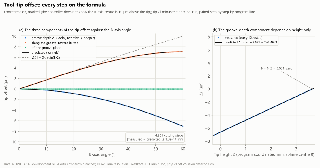
Error terms on, marked: the tool-tip offset of every cutting step (on minus nominal, paired by program line). (a) Split into the groove-depth (radial), along-the-groove (toward its top) and off-plane components against the B axis' angle: dots measured, black lines the same components of the formula dz·(−sin B·cos C, −sin B·sin C, 1 − cos B), grey dashes |ΔCl| = 2dz·sin(B/2). (b) The groove-depth component against the tip height Z, on the straight line −dz·(3.631 − Z)/5.4943. 4,961 cutting steps, |measured − predicted| ≤ 1.8 × 10⁻¹⁴ mm. Symmetric vertical axes, ±10 and ±8 µm. A HiNC 3.2.46 development build with error-term branches.
- The design's spot checks all hold. The last step of line 21 has ΔCl = (+7.0709, −4.9669, +4.9669) µm, line 557 (−7.0710, −4.9824, +4.9824) and line 1113 (+8.6482, +0.1215, +4.9806), the design's values to the fourth decimal.
- The on run has two cutting steps more, one at the end of the X approach on each of lines 20 and 576 (B ≈ 60°). There the tip stands about 7 µm deeper along the sphere's radius, toward its centre (though about 5 µm higher in Z), and touches the stock only with the error on. Steps the nominal run touched and the on run did not: 0.
- The trimmed and whole-program runs agree on their common lines. On lines 1–288 the on run's 277 lines with steps (the nominal's 276) have the same step counts, and the tips and machine coordinates are bit for bit the same, on against on and nominal against nominal. So the per-step formula can be checked on the trimmed copy alone; only the part and the pictures need the whole program.
Spot checks: ΔCl at the last step of each line, µm (the design's three on lines 21, 557 and 1113)
| Line | B | C | Z (mm) | ΔCl (µm) | |ΔCl| |
|---|---|---|---|---|---|
| 20 | 59.974° | 144.756° | −0.2433 | (+7.0711, −4.9961, +4.9961) | 9.996 |
| 21 | 59.781° | 144.914° | −0.2206 | (+7.0709, −4.9669, +4.9669) | 9.967 |
| 116 | 39.979° | 158.669° | 1.8186 | (+5.9849, −2.3372, +2.3372) | 6.837 |
| 204 | 19.953° | 169.869° | 3.1655 | (+3.3593, −0.6003, +0.6003) | 3.465 |
| 374 | 20.076° | 10.196° | 3.1598 | (−3.3785, −0.6076, +0.6076) | 3.486 |
| 462 | 40.095° | 21.402° | 1.8085 | (−5.9965, −2.3502, +2.3502) | 6.856 |
| 557 | 59.883° | 35.169° | −0.2326 | (−7.0710, −4.9824, +4.9824) | 9.982 |
| 577 | 59.625° | −69.313° | −0.2064 | (−3.0477, +8.0711, +4.9434) | 9.943 |
| 671 | 40.038° | −55.672° | 1.8094 | (−3.6277, +5.3125, +2.3438) | 6.847 |
| 759 | 20.028° | −44.377° | 3.1580 | (−2.4478, +2.3952, +0.6047) | 3.478 |
| 929 | 19.982° | 155.643° | 3.1601 | (+3.1131, −1.4093, +0.6020) | 3.470 |
| 1018 | 40.099° | 166.999° | 1.8041 | (+6.2760, −1.4490, +2.3506) | 6.857 |
| 1113 | 59.872° | 180.805° | −0.2353 | (+8.6482, +0.1215, +4.9806) | 9.981 |
The part: the grooves deepen from 0 at their top toward the equator, and the pits and everything else stay
How it was measured: the on run's exported cut has 236,139 vertices, and each was given its signed distance d to the nominal cut (positive = material left, Diff blue; negative = cut too deep, Diff red). The vertices are sorted by geometry:
- The groove: more than 2.8 µm below the stock sphere's radius and within 0.45 mm of the grooves' cutting tips. It splits into the floor, the gentle face the cutter's 30° cone side cuts (only 11.4° off the sphere), and the steep wall, the face its flat end cuts (its normal is the tool axis, 48.6° off the sphere's normal). The two meet at the flat end's rim, the groove's deepest point.
- The pits: the cut faces within 3 mm of the pole blocks.
- The groove edges: the uncut faces within 0.45 mm on either side of the grooves.
- The uncut sphere, and the stem and foot.
The patch of sphere the nominal mesh lacks (327 vertices) and 10 vertices on groove B's sharp edge are left out (dilemma 7).
| Region | Vertices | Median | 5–95 % | 1–99 % | Within 0.5 µm |
|---|---|---|---|---|---|
| Groove floor | 3,243 | −1.93 µm | −6.24…−0.03 | −6.77…+0.04 | (a deviation is expected) |
| Steep wall | 899 | −1.51 µm | −4.58…−0.02 | −5.54…0.00 | (likewise) |
| Pits | 13,784 | 0.00 µm | −0.06…+0.04 | −0.18…+0.12 | 99.91 % |
| Groove edges | 7,707 | 0.00 µm | 0…0 | −0.53…0.00 | 98.94 % |
| Uncut sphere | 123,169 | 0.00 µm | 0…0 | 0…0 | 99.999 % |
| Stem and foot | 86,229 | 0 | 0 | 0 | 100 % |
The prediction vertex by vertex. The vertex distance measures each face's displacement along its own normal, not Δr in the groove's depth. Moving the nominal cutter rigidly by the ΔCl measured at that step and taking the component along the face's normal gives each vertex's prediction. On the floor it comes to 0.97 Δr, as the face lies 11.4° off the sphere; on the wall to 0.71 Δr, as the wall's deviation is ΔCl along the tool axis, −dz·(1 − cos B), −5.0 µm at B 60°. Measured minus this prediction: on the floor's 3,243 vertices a median of +0.02 µm, 5–95 % −0.25 to +0.45 µm, 93.6 % within 0.5 µm; on the wall's 899, +0.01 µm, −0.33 to +1.05 µm, 85.1 % within 0.5 µm. Only the deepest point, at the flat end's rim, reads Δr directly.
| Window (0.1–0.4 mm from the groove ends, or B ± 2.5°) | Steps | B | Tip Z (mm) | Design Δr over the steps (µm) | Floor median (vertices) | Vertex by vertex | Wall median (vertices) | Vertex by vertex | Deepest point |
|---|---|---|---|---|---|---|---|---|---|
| The four groove ends | 149 | 57.5–59.8° | −0.22…+0.04 | −7.01…−6.54 | −6.45 (127) | −6.54 | −4.63 (28) | −4.82 | −7.33 |
| B ≈ 50° | 380 | 47.5–52.5° | 0.60–1.11 | −5.53…−4.58 | −4.88 (255) | −4.96 | −3.53 (84) | −3.55 | −5.15 |
| B ≈ 40° | 360 | 37.5–42.5° | 1.59–2.03 | −3.71…−2.92 | −3.20 (284) | −3.20 | −2.27 (82) | −2.34 | −3.17 |
| B ≈ 30° | 351 | 27.5–32.5° | 2.41–2.75 | −2.22…−1.60 | −1.79 (277) | −1.84 | −1.26 (77) | −1.37 | −1.47 |
| B ≈ 20° | 344 | 17.5–22.5° | 3.04–3.27 | −1.08…−0.65 | −0.82 (285) | −0.83 | −0.57 (70) | −0.60 | −0.73 |
| B ≈ 10° | 340 | 7.5–12.5° | 3.44–3.56 | −0.34…−0.12 | −0.21 (279) | −0.21 | −0.13 (58) | −0.16 | −0.31 |
| Groove top (B < 5°) | 301 | 0.12–4.99° | 3.60–3.63 | −0.06…0 | −0.03 (152) | −0.03 | −0.01 (55) | −0.01 | 0.00 |
The plan's predictions (B ≈ 50° −5.05, 40° −3.31, 30° −1.89, 20° −0.86 and 10° −0.22 µm, −7.0 µm at the groove ends) are Δr at the window's centre; the range of Δr over each window's steps is in the fifth column.
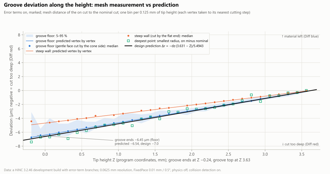
The groove's deviation along its height (the vertex distance of the on cut to the nominal cut, one bin per 0.125 mm of tip height): blue dots the floor's median with a 5–95 % band, orange dots the steep wall's median, green squares the deepest point (the on run's smallest radius minus the nominal's; one vertex per bin, scattering by up to ±0.9 µm with how the mesh samples the flat end's sharp rim), thin lines the prediction vertex by vertex from the cutter moved rigidly by ΔCl, and the black line the design's prediction Δr. The floor reads 0.97 Δr and the wall 0.71 Δr, both as the vertex-by-vertex prediction; −6.45 µm on the floor at the groove ends. Symmetric vertical axis, ±8 µm; negative = cut too deep. A HiNC 3.2.46 development build with error-term branches.
- The 31 bins' floor medians lie −0.005 to +0.29 µm from the formula −dz·(3.631 − Z)/5.4943 (median +0.15 µm); the deepest points −0.88 to +0.86 µm (median +0.06 µm). The deepest point of a bin is a single vertex on the flat end's sharp rim, and the 0.0625 mm mesh samples that rim at different places in the two cuts, so it scatters; the floor has tens to hundreds of vertices per bin, and its medians hold steady.
- The four groove ends one by one: the floor reads −6.47 µm at groove A's start (27 vertices), −6.29 at its end (32), −6.56 at groove B's start (31) and −6.44 µm at its end (37); the deepest points −6.69, −6.71, −6.73 and −8.11 µm.
- Within 0.1 mm of each groove's start and end, the 7 µm shift along the groove leaves a short stretch of paired deviations, negative and positive: −7.06 to +3.23 µm at groove A's start, −7.20 to +2.94 at its end, −6.80 to +2.74 at groove B's start and −7.44 to +2.31 µm at its end (search values, within 8 µm, not checked exactly). That is the groove's end moving, not a depth error; the windows keep 0.1 mm clear of the end points.
- The groove widens. The design only wrote that the groove widens with the V cutter's 30° half-angle, without a number. The floor rises to the stock surface at 11.37° and the wall at 48.63°, so a groove |Δr| deeper is 5.86 |Δr| wider at its mouth, about 41 µm at the ends. A rough reading on the mesh, the mouth sampled by the 0.0625 mm grid: +26.9 µm at the ends, +28.9 at B ≈ 50°, +19.6 at 40°, +14.2 at 30°, +1.6 at 20°, +1.3 at 10° and 0.0 µm at the top, against 39.6, 29.6, 19.4, 11.1, 5.0, 1.3 and 0.1 µm derived. The windows differ by up to 12.7 µm, so only the trend can be told.
- The two pits: the on run's cut comes closest to the centre at 3.63084 mm (line 289, the vertex (0, 0, 3.63084)) and 4.52138 mm (lines 844–845, the vertex (1.5625, 2.1875, 3.63542)), as the nominal cut does; 99.91 % of the pit region's 13,784 vertices lie within 0.5 µm. The program's error (the pits at the pole, B ≈ 0) and the machine's (the groove depth growing with B) leave different fingerprints.
- The whole cut. Leaving out the patch the nominal mesh lacks (327 vertices), 98.5 % of the other 235,812 vertices lie within 0.5 µm. The lowest reading is −19.42 µm, on groove B's sharp bottom edge, a real mesh difference by exact distance, as the two cuts sample that edge differently (30 vertices on the two grooves' edges lie beyond 8 µm). The highest is +4.41 µm, on groove B's edge at B ≈ 31° (a search value, not checked exactly); at the groove ends, at most +3.23 µm of material is left. Only the two grooves move away from 0.
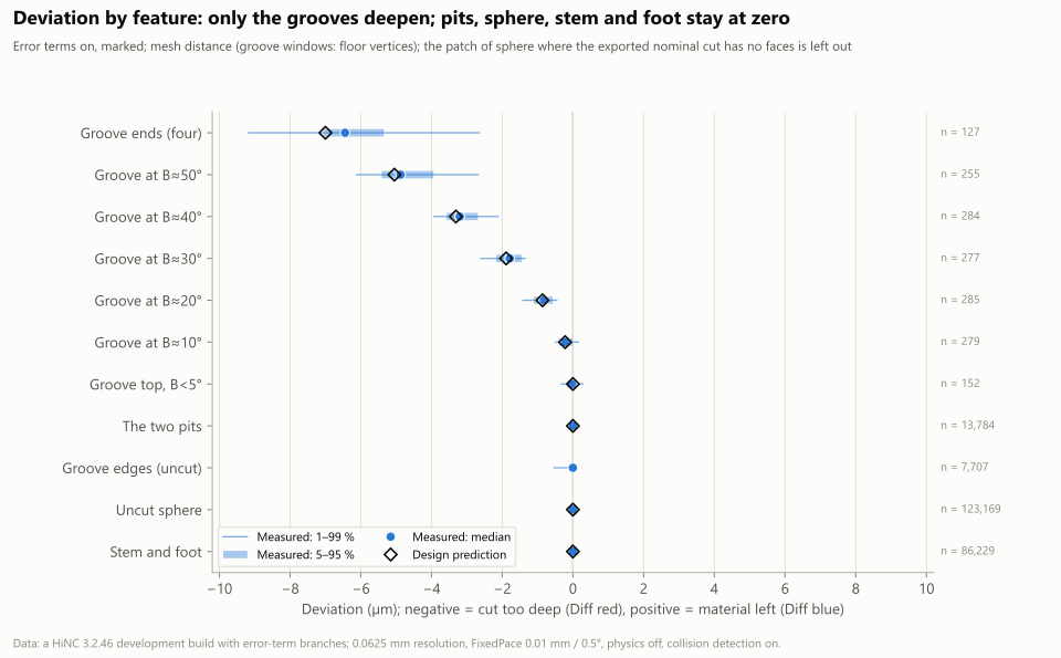
Deviation by feature: the groove windows (floor vertices), the two pits, the uncut faces beside the grooves, the uncut sphere, the stem and the foot; thick bar 5–95 %, thin line 1–99 %, dot the median, black diamond the design's prediction. −6.45 µm at the groove ends (design −7.0), falling to 0 at the groove top; the pits, the sphere, the stem and the foot at 0. The patch of sphere the exported nominal cut lacks is left out (dilemma 7). Symmetric horizontal axis, ±10 µm. A HiNC 3.2.46 development build with error-term branches.
The controller that knows the error (unmarked): bit for bit the one that does not
This run cleared TipOffB's mark, kept the switch on and typed in the same G54 Z +0.010 as the on run;
it played the trimmed copy only. The program is in machine coordinates (X Y Z B C, no G43.4, no G68,
not CL), so the controller sends MC = program + G54 without going through the kinematic chain
(what a mark changes): knowing the error, it has
nowhere to correct it.
- The machine coordinates: X, Y, Z, B and C of the 3,037 paired steps are the marked run's, bit for bit.
- The tip and the tool axis: within 1.8 × 10⁻¹⁵ mm and 2.3 × 10⁻¹⁶.
- The cut: the file of its vertex distances is the same byte for byte, and so are the eight numbers
of
Diff--Stats. - The one difference: line 16, the C0 → C144.756 positioning in the air with the tool parked 14.7 mm from the C axis, takes 2,807 steps marked and 2,806 unmarked, with the same end points. A line's step count is the larger of “tip chord / 0.01 mm” and “rotation / 0.5°”, and the tip is the controller's own: on the nominal chain when the error is marked (the tip 14.7247 mm from the C axis, a chord of 28.0674 mm, 2,806.74 → 2,807), with the error when it is not (14.7162 mm, 28.0514 mm, 2,805.14 → 2,806). A consistency read off the numbers, not traced in the code (dilemma 5).
- The cure is in the post-processor. To put the tip back on the program, every block would have to read X′ = X + dz·sin B and Z′ = Z − dz·(1 − cos B), with the touch-off's G54: +8.66 and −5.0 µm at B 60°. Derived from the formula, not played. Or the tip goes back onto the B axis on the machine. Only a program under RTCP gets the benefit of a calibrated controller.
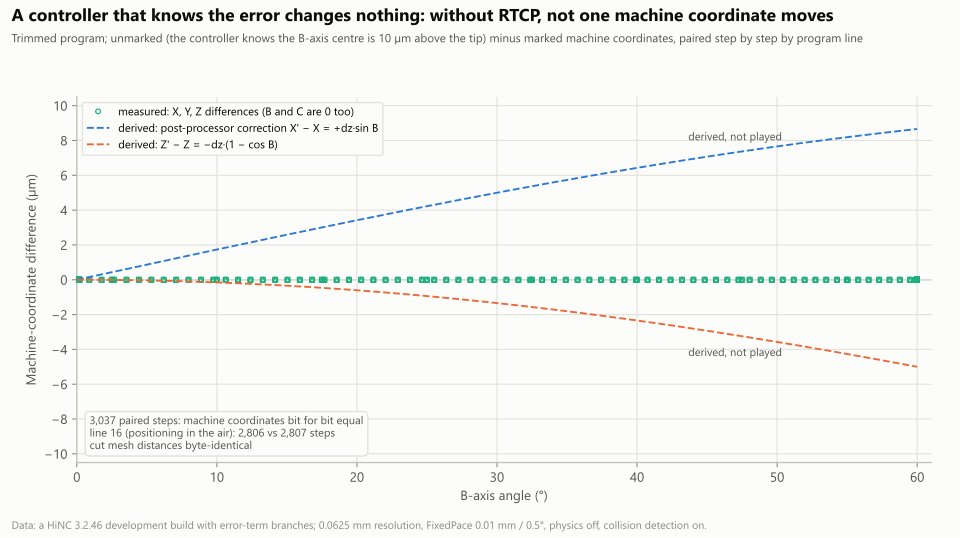
What the controller that knows the error (unmarked) moved instead: in the trimmed program, the unmarked minus the marked machine coordinates are 0 for X, Y, Z, B and C at all 3,037 paired steps (the program is in machine coordinates without RTCP, so the controller does not use the kinematic chain); dashed, the correction a post-processor would have to write into every block to put the tip back on the program, X′ − X = +dz·sin B and Z′ − Z = −dz·(1 − cos B) (derived from the formula, not played). A HiNC 3.2.46 development build with error-term branches.
The control run and the comparison pictures
The control run (switch off, with a Diff) is the nominal run played again: its tips, machine coordinates
and IsTouched are the same at all 16,018 steps (the decompressed series have the same MD5), and its
mesh's 235,904 vertices all lie within 5.0 × 10⁻¹⁰ mm, the floating-point noise of two nearly identical
meshes measured against each other. The spindle prerequisite (No Transform → Dynamic Rotation, bound to
Spindle) did not change the cut. The evidence for that is not this run, as the nominal and the control
both carry the prerequisite and their equality only shows that the play repeats, but the pits lying
where the base case found them without it (sim1 3.6308, sim2 4.5214 mm).
The two pictures below alternate in place at one camera between the error terms on (marked) and off (the control). They put the recorded stock back on the canvas with its Diff, without replaying; the cameras are HiNC's default isometric and top views, zoomed in with the mouse wheel. Read back from the captures' hues:
- Isometric view: of its 110,458 Diff pixels, 766 lie below −1 µm and 77 below −5 µm, the lowest at −7.0 µm.
- Top view: of its 215,759 Diff pixels, 2,019 lie below −1 µm, the lowest at −7.0 µm.
- The blue side has only scattered pixels, each within 2 pixels of one cut more than 1 µm too deep: in the isometric view 7 read above +1 µm, at most +4.8 µm; in the top view 14, the highest a single dark pixel reading +7.0 µm (RGB 19, 19, 130, on the left silhouette), the next +3.9 µm. A single pixel does not make material left: on the mesh, the most left at a groove end is +3.23 µm.
- The control's two views have no pixel beyond ±0.2 µm.
- The front view shows only the stem, the foot and the lower half of the sphere, with no groove in it (no pixel beyond ±0.1 µm), so no front comparison was made.
The geometry difference on the execution page (isometric view) of the sphere, the stem and the foot, alternating in place between error terms on (marked) and off (the control). With them on, groove A turns from green at its top to yellow and red at its end near the equator, cut 6–7 µm too deep there; groove B shows only as a sliver on the left silhouette. The pits, the uncut sphere, the stem and the foot are green; with the error terms off, everything is green. Each frame equals its raw capture pixel for pixel on the part and the colour bar. Diff colour scale ±0.007 mm (red = cut too deep, blue = material left, green = 0, both signs weighted alike); 0.0625 mm; a HiNC 3.2.46 development build with error-term branches.
The same alternation from the top (the sphere and the foot; the stem hides under the sphere). Each groove turns from green at its top to yellow and red toward its two ends near the equator: the two tools share the one machine error. The two pits at the pole, the uncut sphere and the foot stay green; with the error terms off, everything is green. Scale, grid and build as above.
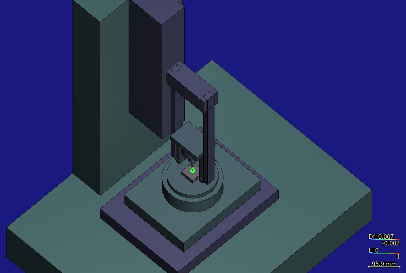
The session of the picture at the top of the page, zoomed out: the generic five-axis machine with a swivel head B and a table C, built for the case with no maker's geometry, and the tool and holder above the Ø11 mm sphere. A HiNC 3.2.46 development build with error-term branches.
Diff--Stats of the four runs with a Diff
| Run | Reported leaves | Surface leaves before comparison | Expanded on demand | New nodes | NaN leaves | Measured wires | Unmeasured wires | Target triangles |
|---|---|---|---|---|---|---|---|---|
| f-on | 246,465 | 229,295 | 11,123 | 28,293 | 72 | 972,738 | 732 | 454,761 |
| f-control | 246,196 | 229,026 | 11,126 | 28,296 | 1 | 972,095 | 323 | 454,761 |
| t-on | 243,594 | 226,420 | 11,431 | 28,605 | 1 | 961,801 | 304 | 449,511 |
| t-unmarked | 243,594 | 226,420 | 11,431 | 28,605 | 1 | 961,801 | 304 | 449,511 |
- The nominal runs make no Diff. The trimmed runs' target is the trimmed nominal cut, hence their different triangle count.
- The on run has 71 NaN leaves and 409 unmeasured wires more than the control, with no positions in the records (dilemma 7). The spot below the end of groove B in the holder picture lies in the patch the nominal mesh lacks and may be those NaN leaves (not verified).
What the runs cost
All runs used private instances of a HiNC 3.2.46 development build with error-term branches on the shared 32-thread server. VmHWM is given in GB (bytes ÷ 10⁹), with GiB (bytes ÷ 2³⁰) in brackets.
| Play | Grid | Steps | Wall time | Steps per second | Peak memory (VmHWM) |
|---|---|---|---|---|---|
| t-nominal | 0.0625 mm | 5,843 | 720.9 s | 8.1 | 2.70 GB (2.51 GiB) |
| t-unmarked | 0.0625 mm | 5,843 | 640.7 s | 9.1 | 2.98 GB (2.77 GiB) |
| t-on | 0.0625 mm | 5,844 | 600.6 s | 9.7 | 2.77 GB (2.58 GiB) |
| f-nominal | 0.0625 mm | 16,018 | 1,251.3 s | 12.8 | 3.45 GB (3.21 GiB) |
| f-control | 0.0625 mm | 16,018 | 1,261.4 s | 12.7 | 3.67 GB (3.42 GiB) |
| f-on | 0.0625 mm | 16,019 | 1,236.4 s | 13.0 | 3.55 GB (3.30 GiB) |
- The whole program: three runs, 3,749.1 s (62.5 minutes), 20.6–21.0 minutes and at most 3.67 GB each, against the plan's estimate of about 20 minutes and at most 5 GB a run. The instance was restarted before each run, so each VmHWM is that run's own peak: loading, playing, the Diff and the export.
- The trimmed copy: three runs, 1,962.2 s (32.7 minutes), 10.0–12.0 minutes each, above the plan's estimate of 6–8 minutes. The trimmed program plays 8–10 steps a second and the whole program about 13; why was not measured, as the records keep only each run's whole wall time. The trimmed runs played one after another on the same private instance, and the records do not say whether it was restarted between them, so their peaks are read only as each run's upper bound and are not compared with one another.
- In all, the build and the six plays took about 95 minutes of server time (5,711.3 s of plays). The times: build on 2026-10-06 at 21:42:51–21:42:58, trimmed runs 21:43:30–22:16:22, whole-program runs on 2026-10-07 at 01:34:18–02:36:57.
- Wall time runs from the start of the play to the poll that read
Finished; the poll comes every 5 s, so a wall time can be up to 5 s late. Whether other work shared the server at the time is not in the records. - The analysis: one full rerun of the analysis script takes about 5.5 minutes.
What it means
For a machining engineer.
- A five-axis program for a swivel head B, written in machine coordinates without RTCP, is right only if the tool tip sits exactly on the B axis. With the tip 10 µm low, each groove is cut deeper from its top toward the equator, 7 µm at its ends: in this program, 28 % of the 25 µm nominal depth of cut.
- A touch-off at B 0 does not show this error: machine X, Y, B and C do not change at all, and Z differs only by the 10 µm the touch-off types in. Its fingerprint is that the groove depth goes by height alone: measure the groove's depth against height on the part, and dz can be checked and read back.
- A calibrated controller does not help: the program never goes through the kinematic chain, and marked or unmarked, the machine coordinates are the same bit for bit and so are the cut's vertex distances. The correction has to go into the post-processor (X′ = X + dz·sin B, Z′ = Z − dz·(1 − cos B)), or the tip has to go back onto the B axis; only a program under RTCP gets the benefit of calibrated kinematics.
- The program's own error (the pits at the pole, B ≈ 0) and the machine's error (a groove depth growing with B) leave different fingerprints on one sphere, and the simulation tells them apart.
- In HiNC, a constant error of a machine can go into its model, and its shape and size on your own part show before the part is cut.
For a teacher or a student.
- How an offset on the tool side becomes the tip offset e = dz·(a0 − a(B)), and why it depends only on B; why a translation upstream of B leaves nothing on this machine.
- Why the tool's constant 48.6° to the sphere makes the groove-depth error go by height alone: Δr = −dz·(3.631 − Z)/5.4943.
- That a vertex distance measures each face's displacement along its own normal: the floor reads 0.97 Δr, the wall 0.71 Δr, and only the deepest point reads Δr.
- That marked and unmarked stand for uncalibrated and calibrated kinematics; on a program in machine coordinates they are the same, and the only difference is a step count set by the controller's own tip chord.
For someone weighing the approach.
- Cost. The build and six plays took about 95 minutes of server time, at a peak memory of at most 3.67 GB a run.
- Predictions, written before the first play: the tip formula holds at every cutting step within 1.8 × 10⁻¹⁴ mm; the floor medians lie within 0.29 µm of the plan's Δr formula; the pits are where the base case found them. The vertex-by-vertex model added after the plays, the cutter moved rigidly by the measured ΔCl, matches the floor medians within 0.1 µm.
- What missed, written as measured: the runs paired by program line instead of as the plan said; zero offset at B = 0 only once the touch-off takes effect (criterion 3's second half failed as written); the unmarked run one step fewer on line 16 (criterion 4 failed as written); the steep wall not fitting the floor's formula; a patch of faces missing in the exported nominal cut.
Honest limits
- One error only, and a constant one. Only the tip low by dz along the tool axis is here. A real B head has other errors at the same time: the tip off the B axis along X at B = 0, dx, which would move the groove ends outward by 0.36·dx and off the groove's plane by 0.81·dx, so the grooves would no longer be plane circles and the depth would no longer go by height alone; a tilt of the B axis; a radial run-out of C. An error term holds only a constant; errors that vary with position, backlash, servo mismatch and thermal deformation cannot be put in (Machine Geometric Error). The spindle's thermal growth would make dz change with time, which is exactly the kind this case cannot hold.
- The size and the sign are chosen. 10 µm is a typical value, not a measurement. The companion article is not open access and was not read, so the authors' tool-setting accuracy is not known (the design puts microscope tool setting on ultra-precision machines at about 1–5 µm). A coefficient can be given: every 1 µm the tip stands low makes the groove ends 0.70 µm deeper. With the tip above the B axis' centre instead (dz reversed), every deviation reverses: the grooves grow shallower toward the equator and keep 7 µm of material at their ends.
- The touch-off is typed, and its pose assumed. HiNC's P0 measures on the nominal chain and does not take the error in as a real touch-off would; the G54 Z +0.010 of the two runs with the error on is derived, assuming a touch-off at B = 0. Before the touch-off takes effect (the start pose, and after a tool change before a Z word) the tip stands 10 µm low, as it would on a real machine.
- T01 and T04 have the same length. On a real machine the second tool would have a length error of its own; the machine's error term stands only for the part the two tools share.
- Geometry only. Physics is off: no cutting force, no deflection, no heat.
- Reading a 0.0625 mm mesh. The groove itself is smaller than a cell (25 µm deep at the tip, 62.5 µm at its deepest line), so the groove's widening has only a derived value and a rough reading (the windows differ from the derivation by up to 13 µm); the deepest point is one vertex per bin and scatters by ±0.9 µm; and the two cuts round the grooves' sharp edges differently (30 vertices on the two grooves' bottom edges at −19.4 to −8.1 µm, real mesh differences by exact distance). This case runs Fixed Pace motion (0.01 mm / 0.5°): each step removes the hull of the cutter between its two poses (dilemma 8), so there are none of the ridges between unswept steps that Feed Per Cycle motion leaves, and the two runs' cutting lines have the same step counts.
- The exported nominal cut lacks a patch of faces below the end of groove B (dilemma 7): that patch's 327 vertices and 10 vertices on groove B's sharp edge are left out of the region statistics.
- No unmarked run of the whole program, and no unmarked picture. The unmarked run played the trimmed copy only, and its cut's vertex distances are byte for byte the marked run's, so a picture of it would show the same frame twice. So there is no “controller unaware / aware” alternation, only on against off.
- The authors' fixed programs were not played. exp1 and exp2 follow the same law as sim1, but need 0.03125 mm, about 45 minutes a run: at their inserted pole blocks the tip stands still while C turns slowly, and with the error on the tip only runs a small circle of radius dz·0.0017, still nearly degenerate for the Fixed Pace hull (dilemma 8). The production program, 369 passes, was not played either.
- The wall times are polled, every 5 s, and the records do not say whether other work shared the server.
What a reader can take to their own case
- Ask which assumption the program itself rests on. A five-axis program in machine coordinates is computed for one tool length and one pivot. The error that shows on the part is the one that breaks that assumption — here the tip off the B axis — not necessarily the usual one for a rotary axis.
- Put a tool-side error where the manual puts it. On a B head the spindle's error term goes between B and the spindle branch (where an error term may go). Bind the Spindle role first, with its rotation through the tool tip, so that the spindle angle leaves the cut alone (Roles).
- Type in the work offset a touch-off would find, at the touch-off's pose. P0 measures on the nominal chain (work offsets on a machine with error terms); steps taken before the touch-off takes effect are not a fault of the model.
- Pair two runs by program line when they differ. The manual warns that runs with and without error terms can differ in their number of steps; when a typed work offset also moves the machine coordinates, pairing by program line still works.
- Read each face along its own normal. Predict a cut face by moving the cutter rigidly by the measured ΔCl: here the floor reads 0.97 Δr, the wall 0.71 Δr, and only the deepest point Δr.
- Check extreme vertex distances exactly, and check the reference mesh too. Here the largest readings were real distances, to a patch of faces missing in the exported nominal cut, not a cut.
- On a program in machine coordinates, a calibrated controller changes nothing. Every error in the chain is cut into the part, marked or not (what a mark changes); correct it in the post-processor, or set the tool again.
- Tell the program's error from the machine's by their fingerprints: pits at B ≈ 0 against a depth error that grows with B and goes by height alone.
- Check the build and the formula on a short copy of the program first. The trimmed copy's runs gave the same tips and machine coordinates as the whole program's on their common lines.
- Write the fallback's trigger as numbers before the first play, and say which half of it could be measured when the choice was made.
Source and licence
The NC programs come from a data set on Mendeley Data:
- Data set: Liqiang Wu, Hanzhong Liu, Zhipeng Cui, Wenjun Zong, NC codes for a research in
fabrication of randomly distributed V grooves on a spherical surface, Mendeley Data, version 1,
published 2023-09-04, https://doi.org/10.17632/bcskc575nm.1; landing page
https://data.mendeley.com/datasets/bcskc575nm/1. Search terms if the links move:
NC codes for a research in fabrication of randomly distributed V grooves on a spherical surface,bcskc575nm,simulation_singular1_without_singularity_algorithm. - Files: five G-code files —
simulation_singular1_without_singularity_algorithm.txt(the sim1 this page plays),simulation_singular2_without_singularity_algorithm.txt,experiment_singular1_with_singularity_algorithm.txt,experiment_singular2_with_singularity_algorithm.txtandrandom_micro_V_structures_machining.txt, the production program — and the record's description. No README, no licence file, no model, machine, tool or measurement. - Companion article (cited, not read): L. Wu, H. Liu, Z. Cui, W. Zong, “Fabrication of randomly distributed V grooves on the great circles of a spherical surface using ultra-precision five-axis milling”, Precision Engineering 85 (2024) 48–64, https://doi.org/10.1016/j.precisioneng.2023.09.005. The data record does not link it; it was matched by its title and its four authors, who are the data set's creators. It is not open access and was not read; nothing from it is used.
Licence: Creative Commons Attribution 4.0 International (CC BY 4.0), as the data record's licence field gives it, read on 2026-09-29:
You can share, copy and modify this dataset so long as you give appropriate credit, provide a link to the CC BY license, and indicate if changes were made, but you may not do so in a way that suggests the rights holder has endorsed you or your use of the dataset. Note that further permission may be required for any content within the dataset that is identified as belonging to a third party.
Nothing in the data set is marked as belonging to a third party.
Attribution, as the base case's source record gives it:
NC programs: Liqiang Wu, Hanzhong Liu, Zhipeng Cui, Wenjun Zong, “NC codes for a research in fabrication of randomly distributed V grooves on a spherical surface”, Mendeley Data, V1 (2023), https://doi.org/10.17632/bcskc575nm.1. Licensed CC BY 4.0 (https://creativecommons.org/licenses/by/4.0/), provided as-is without warranties (CC BY 4.0 Section 5). Related article: L. Wu, H. Liu, Z. Cui, W. Zong, Precision Engineering 85 (2024) 48-64, https://doi.org/10.1016/j.precisioneng.2023.09.005. The authors do not endorse this case or HiNC. Changes: none to the files; the programs are played as published on a machine, stock, cutter and set-up made for this case.
and, for this page:
The tool-and-holder pictures (and the shorter check runs) play a shortened copy of simulation_singular1: its lines 1–288 unchanged and line 289 stopped at its midpoint.
What was used and changed.
- sim1 is played byte for byte as published. The trimmed check runs and the holder pictures play a
shortened copy,
pose-sim1-line289-half.nc: lines 1–288 unchanged and line 289 stopped at its midpoint. The other four files were not played on this page. - The machine (a generic five-axis machine with the B head through the tool tip and the C table through the sphere centre, no maker's geometry), the stock (an R 5.5193 sphere with a stem and a foot, on a plate), the cutter (a 60° V with a Ø0.1 flat tip) and the holder (Ø3 shrink-fit, 10 mm stick-out) are the base case's choices, not the authors' machine or tools.
- Added for this case: one marked error-term branch on the machine,
TipOffB. Its kind, its size, its sign and the touch-off work offset are the agent's choices; this generic machine has no measurement, and 10 µm is a typical value.
The pictures and the charts. No figure of the data set or of the article is reproduced. The pictures are HiNC captures, and the charts are drawn from HiNC's per-step results and cut meshes. Everything is simulated; nothing was cut. The authors took no part in this case and do not endorse it. This site offers no download; fetch the files from Mendeley Data.
See Also
- Building Virtual Machine Tools: Error terms — where an error term may go, a spindle housing's error on a B head among them, what a mark changes, the Enable Error Terms switch, and work offsets on a machine with error terms
- Building Virtual Machine Tools: Roles — the Spindle role, which needs a Dynamic Rotation turning about the tool mount's axis
- Kinematic Topology: Error-Term Branches — the nominal chain the controller solves, and which errors it can see
- Machining Issues Outside the Model: Machine Geometric Error — the machine errors the model leaves out
- Geometry Validation — the geometry difference, its detection radius and its colour scale
- Program Zero Alignment — P0, and typing in a measured work offset
- A 17-Inch Forged Aluminium Wheel on a C Table 20 µm Off Centre — a five-axis case under RTCP (
G43.4), where the controller that knows the error cuts the nominal wheel - The NIST Cone Frustum on a C Axis 10 µm Off Centre — another five-axis case under RTCP, with the touch-off's work offset typed in
- Showcase — the other cases, and how a case page reads